Introduction

A simple guide on how to replace the processor of your Lenovo T530/T530i

  1. 2PrjuIlkIpDCKFeI
    2PrjuIlkIpDCKFeI
    NmufGfTBGGZQT1Tb
    • Ensure that the laptop is disconnected from the wall charger, and that the laptop is entirely powered off before following any of the steps below.

    • Flip your laptop upside down, so that the keyboard is facing down.

  2. taReXrsbNj14l1iu
    taReXrsbNj14l1iu
    GoFyZALGIY3b6k1d
    • Locate the latch located on the battery near the top of the laptop.

    • Using your finger, slide the latch to the right-most (Unlocked) position.

    • None of this should require an exhuberant amount of force.

  3. OYXXXGYitNL2LT4B
    OYXXXGYitNL2LT4B
    HPEmEPkAkT63R51G
    • You can now pull the battery away from the laptop. When pulling the battery out, ensure to pull it out straight.

  4. INyYpFfnSCmQUsJZ
    INyYpFfnSCmQUsJZ
    vD4Dk3iSlrx45VlD
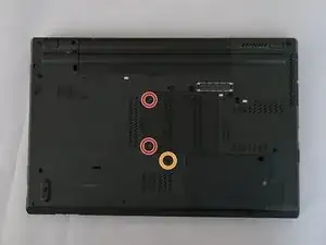
    • Using a Phillips #00 screwdriver, unscrew the following screws, and then remove the cover.

    • Using a Phillips #00 screwdriver, remove the screw. This is one of the two screws that are holding in the keyboard.

  5. MkPDYS3AjrpIMf5x
    • Using a Phillips #00 screwdriver, unscrew the highlighted screw. This is the last screw securing the keyboard to the laptop.

  6. n24tDWt4YxujOAh2
    n24tDWt4YxujOAh2
    IO2ygD1QWyUNhDDh
    • Flip the laptop right-side up, with the keyboard facing towards you.

    • Open the laptop.

  7. XGY3RONQGabdQYaA
    XGY3RONQGabdQYaA
    SWMVGKVuaHKXI2J6
    lg1ULE1P2IVY6xH1
    • Place each of your two thumbs on the bottom-left and right most corners of the keyboard (towards the arrow keys, and the Fn (Function) key).

    • Gentilly and slowly push the keyboard up (towards the display)

    • Lift the two corners of the keyboard up enough to see the ribbon cable below.

    • Applying excessive force to the keyboard ribbon connector may result in damage to the system.

  8. 1Qc3sL4tUtFCeP1T
    1Qc3sL4tUtFCeP1T
    WBiTMSNEfUeYBXTN
    KrevUgSFROfBGSWp
    • Angle the keyboard upwards, at a 90° angle.

    • Keep one finger holding the keyboard up, while using the other to disconnect the ribbon cable. To disconnect the ribbon cable, lift it up by the highlighted yellow end.

  9. GXp2tZiuCZa3EWFL
    • The keyboard is now disconnected from the laptop, and you can remove it and place it aside.

  10. HO1E2BBAWiRUwRuO
    • Reconnect the keyboard ribbon cable by pushing it down onto the slot.

  11. SBUNkeCuGksaSuU5
    SBUNkeCuGksaSuU5
    IDuLItn5xCqFh5BZ
    u6SdPmUfaCIXDSG5
    • Guide the keyboards top edge underneath the frame.

    • 2nd Image was copied from the Lenovo T530/T530i/W530 Service Manual.

  12. DoP2NhIIvdTIXPqm
    DoP2NhIIvdTIXPqm
    RMyQogVwyFXv3w1F
    • Push the keyboard down, then pull it back towards your trackpad.

  13. oeQYUaBQTID1cK5m
    • Using a Phillips #00 screwdriver, re-screw the highlighted screws.

  14. DJD5p6CuagJTi2YT
    DJD5p6CuagJTi2YT
    lkyOJBVOQOfupwuD
    Q1NgXbJjmcwUc2GM
    • Reinsert the bottom memory cover, ensuring all clips are in place.

    • Using a Phillips #00 tighten the two highlighted screws.

  15. OMyybHiAqpTwVOEr
    • Using a Philips M2 screwdriver, remove the 2 screws highlighted in yellow. The bottom screw is underneath the hard drive, which should have already been removed.

  16. GafbF1KDWbnj5aEG
    • Pull the ExpressCard from the ridges on the side, it should pop out of place.

  17. xwnnuIRcdnpQUYsP
    • Using a Philips 2 screwdriver, remove the 7 screws highlighted in red.

  18. 1tdkevMpDT4oD5Uv
    1tdkevMpDT4oD5Uv
    mTQJLChP4XRYExMu
    • Begin by prying the keyboard bezel up from the edges using a guitar pick or shim between the keyboard bezel and the housing of the laptop, as highlighted in red.

  19. lqTZqoXGqNfSavOC
    lqTZqoXGqNfSavOC
    lV4pSqFrVZg4BIml
    ogFAFmKbdPNFIN4Z
    • Locate the ribbon cable near the trackpad highlighted in red, use a flathead screwdriver or some other flat object to push up the locking leaver to then free the ribbon connector.

  20. e2ebfE44YjWPyKW3
    e2ebfE44YjWPyKW3
    SxTZNXYWZIBIFccR
    • Grab the keyboard bezel from the two bottom corners (near the trackpad) and lift the bezel up- and away from the display (away from you).

  21. qDW2OjCc2IRD6xjd
    qDW2OjCc2IRD6xjd
    ZXtMWGKZOGaRx2oK
    • Locate the Speaker, on the middle-left of the laptop.

    • Remove the two highlighted silver Phillips #00 screws

    • Now that the two screws have been removed, you can pull the speaker to the side, as seen in the second photo.

  22. CmVrJyZvBKTVyPrF
    CmVrJyZvBKTVyPrF
    JGpQ5CZjAv4CFQFM
    • Using a Phillips #00, loosten the screws in the order below, however do not entirely remove them from the heatsink.

    • Loosten the top-left screw

    • Loosten the bottom-right screw

    • Loosten the bottom-left screw

    • Loosten the top-right screw

    • If your laptop is equiped with a dedicated gpu, there may be more screws which you will need to remove.

  23. LKiEDfEYO2vYQ5Lv
    LKiEDfEYO2vYQ5Lv
    jP3J3wcQIXrHvRys
    yYMqQt6mYnED3AWy
    • Use your hand to unplug the fan cable for the heatsink.

    • Using your hand, gently pull the heatsink away from the display (towards the trackpad) enough to move it up.

    • This process should not require an exhuberant amount of force, if there is any tension- inspect for any cables or screws impeding you.

  24. lAcyArrUKUUoycBb
    lAcyArrUKUUoycBb
    PwRpjItuPsrUOUpw
    I34x1pLaqMFxYIUf
    • Locate the CPU socket, located near the middle of where the heatsink was, using a flathead screwdriver rotate the arrow to the unlock position with the corresponding unlocked padlock icon.

    • This is the time to use Q-tips to clear any thermal compound (thermal paste) on the processor.

    • Lift up the processor from the edges.

    • Do not touch the processor by the gold pins, and do not touch the die, touching either could cause potentially unrepairable damage.

  25. ZupED2FRUuJEhWIR
    ZupED2FRUuJEhWIR
    gKBJFdJUSjIOhDxh
    VQnEBlJ3MQKsXRoe
    • Near the top-left of the socket there should be a small triangle, as highlighted in red.

    • The first photo was downloaded from Wikipedia.

    • Guide the processor into the slot so the golden triangle on the processor lines up with the triangle on the socket.

  26. rbTIIuoDqKE6x2Mx
    • Using your syringe of thermal paste, put a pea-sized amount of thermal paste onto the die, highlighted in red.

    • If an excess amount of thermal paste is used, you can use a Q-Tip to clean some off, the same can be done if thermal paste comes off the die and onto the blue PCB of the processor.

Conclusion

To reassemble your device, follow the instructions wherever neccessary in reverse order.

Albert Stoynov

Member since: 12/09/23

1198 Reputation

0 comments