Introduction

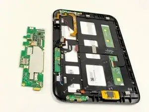
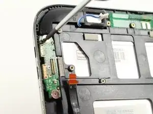
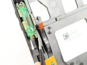
Use this guide to replace the IO board.

  1. HhveJDAeOXSiQoNa
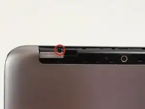
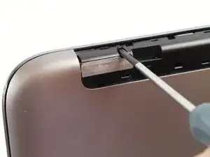
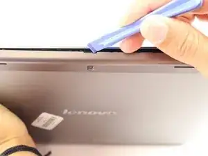
    • Look at the back of the tablet and locate the speakers on top of the rear cover.

    • There is a smaller indentation in the plastic cover that runs across the top of the device.

    • Wedge the plastic opening tool, under the middle of the cover as shown, then push up and the cover will pop off.

    I just want to find out if my sd card is stuck inside how do I remove it without damaging the tablet.

    Tom Mukotora -

  2. QbGg4qsEDU2ZZepj
    QbGg4qsEDU2ZZepj
    MjQWXfTsiLvZGIkP
    • Remove SD card if present.

    • Remove two black 3mm Phillips #00 screws.

  3. atQRWMsJDJifCWSJ
    atQRWMsJDJifCWSJ
    m1ulVXTwwZYNK3RT
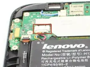
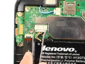
    • Disconnect battery power connector by pinching the connector with tweezers, and sliding it out of the housing.

  4. PHYTJMU4wcOYsBPO
    PHYTJMU4wcOYsBPO
    HQGnoQdt3AuGQT6D
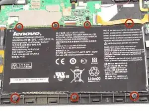
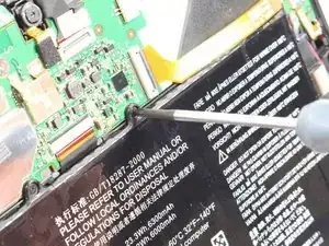
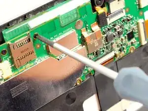
    • Remove seven black 3mm Phillips #00 screws.

    • The top right corner screw is underneath a yellow ribbon. Lift the ribbon up without disconnecting it and unscrew the screw.

  5. 4EHrOWVduVYvfA2U
    4EHrOWVduVYvfA2U
    BNrmJ5mIaxYCfuEJ
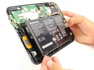
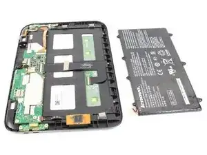
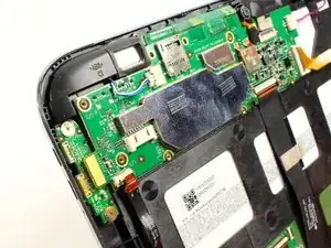
    • Now you can take the battery out in order to either replace it or continue disassembling the device.

    Fantastic advice. After being told by Lenovo I needed to shell out £110 for a new mobo when it just had a charging socket issue I took it upon myself to see if I could fix it. This website helped take it apart and I found that the charging socket is just a micro daughter-board.

    If you have a problem with charging then go to http://www.replacebase.co.uk and search for Lenovo A2109A. They have all the parts.

    I replaced the daughter board and battery for about £10 incl del. Parts arrived yesterday and I have fitted. Works a treat. Not sure what amazes me the most, the low cost of the parts and excellent service by replacebase or the fact Lenovo tried to rip me off.

    These instructions are spot on.

    Well done

    Goon'

    Andy Blunn -

  6. FHVlxFOkSPsoIAYG
    FHVlxFOkSPsoIAYG
    LdLuBCmqWwabEUOw
    qRGKLRrFkgCQtwXD
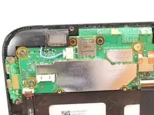
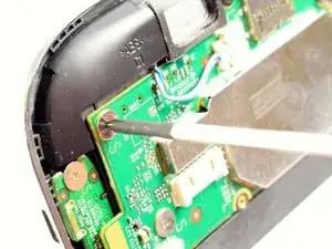
    • Remove two black 3mm Phillips #00 screws.

    • Remove three silver 1.8 mm Phillips #00 screws.

    You can skip step 8 and step 10, leave these connectors in place (just remove the speaker connector in step 9) lift board enough to remove I/O board and leave most connectors in place.

    green1eng -

  7. qT3vyhjERKaLf5hb
    qT3vyhjERKaLf5hb
    IqhCMWwe4ubwRBhh
    FLMYRGDlWQtRwsPO
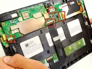
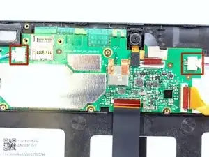
    • Use tweezers to flip up the small black plastic locks on all four connections.

    • Carefully remove each of the exposed ribbons.

  8. QwpjpGxEDiSaojvT
    QwpjpGxEDiSaojvT
    3KRFyQCPOXOs4G4D
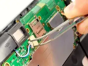
    • Disconnect the two speaker connectors by pinching them with tweezers and sliding them out from the system board housing.

  9. wWHBiHB2S4vVXL4t
    wWHBiHB2S4vVXL4t
    fCAnBoSReOQQcspF
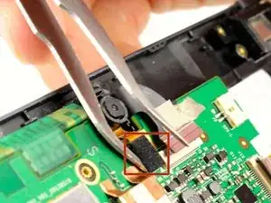
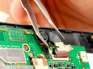
    • Use tweezers or your finger nail to disconnect the camera attachment by flipping up the black rectangular connector.

  10. WSG2pOeLc2F3JR5Y
    WSG2pOeLc2F3JR5Y
    fK4rbkvFaxfq5ICY
    GeDjpViYjKKrIeuH
    • Disconnect the HDMI connection with the system board

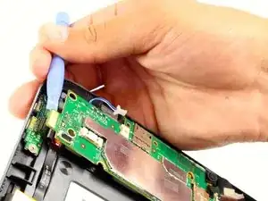
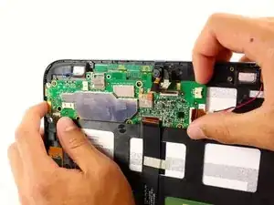
    • Use a plastic opening tool to pry up the system board, and you will hear a pop as it comes free.

    • Slide out the system board from its housing tab on the upper right corner.

    • Pull the board slowly away from the tab, and it will pop out.

  11. ASNs14GA13MQrPwk
    ASNs14GA13MQrPwk
    nr2djwsvl1ZVHeuk
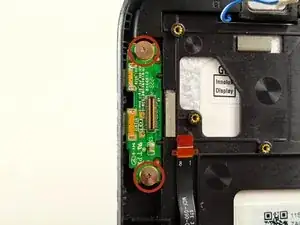
    • Remove the following two screws:

    • M 5.3 x 1.75 mm #00 phillips screws (silver)

  12. KtVBDSGXPZgBnM4e
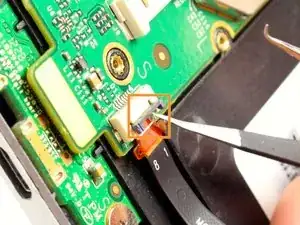
    • Once the screws are out, use the tweezers to pull the board straight out.

Conclusion

To reassemble your device, follow these instructions in reverse order.

Brian

Member since: 22/04/14

565 Reputation

6 comments

Great guide but make sure you REMOVE THE AUX SD CARD FIRST if installed or you will break the card and or card slot.

Other than that, no problems. I got the io board for $26 and I put it in for free.

James Bush -

I need an io board for cheap... I might have to make a guide on how to attempt to repair io card without proper tools and a filed down soldering iron tip

Ember Leona -

Thank you this was helpful. I think I fixed my screen flickers the LCD ribbon is under the battery and the ribbon from the volume board on the right I think that's related to the screen rotation lock. Those needed to be flipped up and reseated. Thanks
Ember Leona -

Thanks Very much

the guide is very clear

i have done the job successfully

omimh -

Excelente guía. Muchas gracias.

Larry Pacheco -

You don't have to remove the 4 connectors in step 8 or the camera attachment in step 10, remove only the speaker connector in step nine and just lift the system board enough to unplug it from the I/O board, then put new I/O board in place and press main board down to it. Be careful when snapping the large back cover in place, I broke the plastic where one of the two small retainer screws go. Pretty easy repair overall.

green1eng -