Introduction
Tools
-
-
Power off the laptop and place it face-down on a non-scratching surface.
-
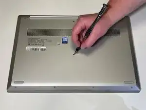
Using a Torx T5 screwdriver head, remove all ten 6 mm screws holding the back panel in place.
-
-
-
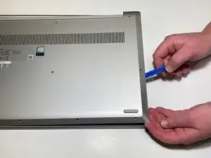
Slide a plastic opening tool underneath the back case near the screen hinges.
-
Gently pry up on either side of the case.
-
-
-
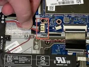
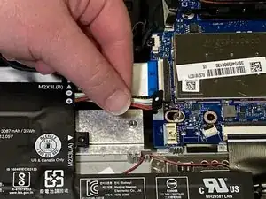
Disconnect the battery cable by gently pulling it straight out of the connector.
-
Remove the battery from the laptop.
-
-
-
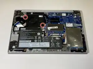
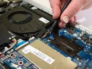
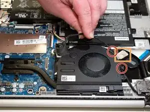
Carefully unwind the black cable that runs between the top of the battery and the bottom of the fan from the grooves along the side of the fan.
-
In order to do so, you will need to pull up the metallic tape that holds the cable in place using either your fingers or a plastic prying tool to lift up the edge.
-
-
-
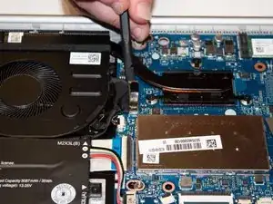
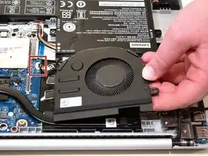
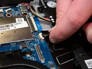
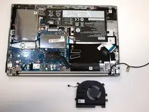
Carefully pick up the fan by the corners and detach the small connector wire by pulling parallel to the device.
-
Remove the fan from the laptop.
-
-
-
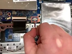
Unplug the wire connecting the speakers to the motherboard.
-
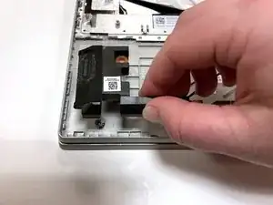
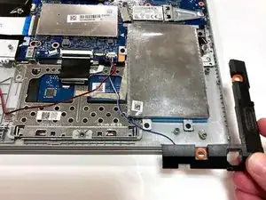
Remove the speakers from each side of the laptop.
-
-
-
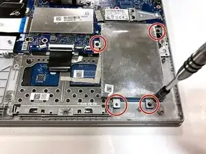
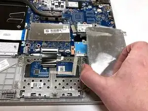
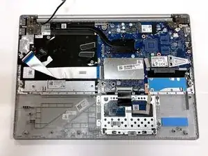
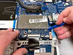
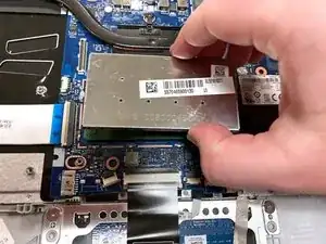
Remove the four 3 mm screws holding the hard drive expansion slot in place using a Phillips #0 screwdriver.
-
-
-
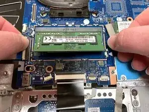
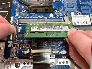
Using your thumbs, gently pull the two metal prongs that secure the RAM outwards.
-
Remove the RAM from the laptop.
-
-
-
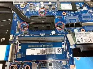
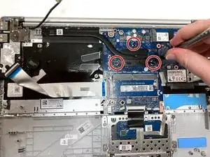
Remove the three 3 mm screws that secure the black heat sink near the top of the computer using a Phillips #0 screwdriver.
-
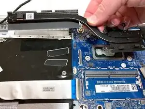
Lift the heat sink vertically to remove it from the laptop.
-
-
-
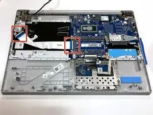
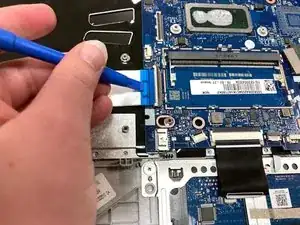
Using an opening tool, carefully flip up the retaining flaps holding the silver video cable in place.
-
Slide the ribbon cable out of each connector.
-
-
-
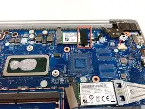
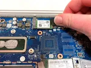
Pull up the black foam adhesive that covers the screw and connectors holding the Wi-Fi card in place.
-
-
-
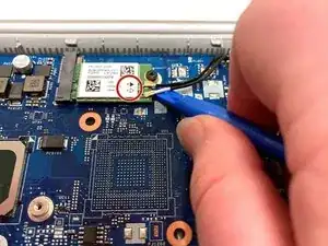
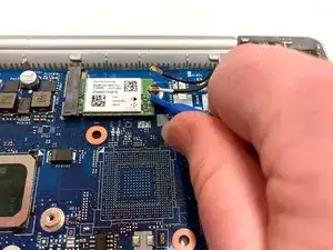
Using an opening tool, lift up on the black and white coaxial cables on the Wi-Fi card and gently pull upward to unplug them.
-
-
-
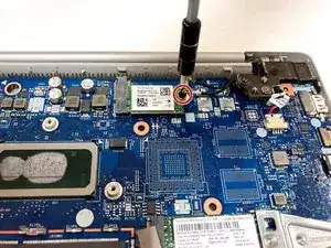
Remove the single 3 mm screw holding the Wi-Fi card in place using a Phillips #0 screwdriver.
-
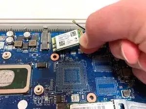
Gently lift the Wi-Fi card out of the computer.
-
-
-
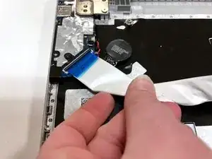
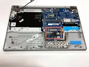
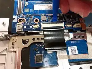
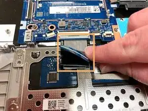
Using an opening tool, flip up the retaining flap that holds the connector to the thin black ribbon cable at the bottom of the motherboard.
-
Gently remove the ribbon cable from its connector.
-
The cable is folded over and connected to itself with an adhesive. Be careful to only pull at the top fold of the cable.
-
-
-
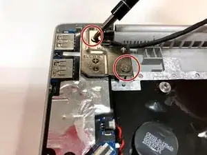
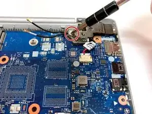
Remove the three total silver 6 mm screws from the hinges of the screen in the top corners of the device using a Phillips #0 screwdriver.
-
-
-
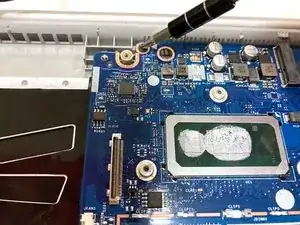
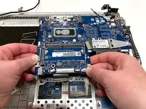
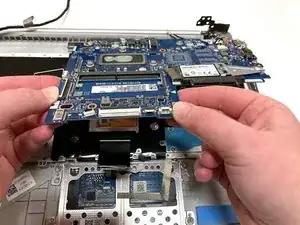
Remove the three 3 mm screws holding the motherboard in place using a Phillips #0 screwdriver.
-
-
-
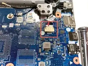
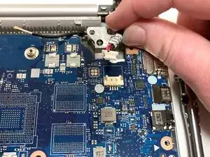
Carefully unplug the black and red wires connected to the upper right corner of the motherboard.
-
-
-
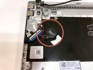
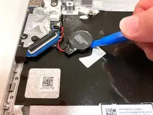
Remove the circular CMOS battery on the far left side of the computer by lifting it with your finger or an opening tool.
-
-
-
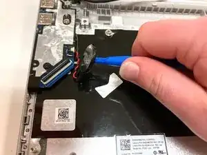
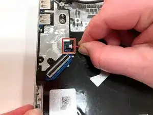
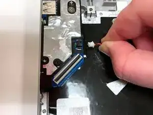
Unplug the bundled red and black wires connecting the CMOS battery to the side of the device.
-
Remove the CMOS battery from the laptop.
-
-
-
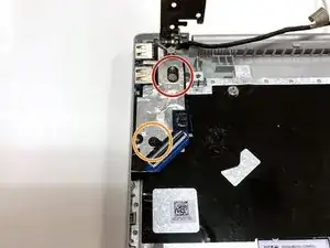
Remove the silver 6 mm screw holding the USB and SD card slots in place in the upper left corner of the device using a Phillips #0 screwdriver.
-
Remove the black 3 mm screw holding the USB and SD card slots in place in the upper left corner of the device using a Phillips #0 screwdriver.
-
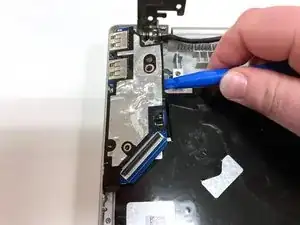
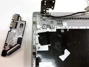
Use an opening tool to pry the port out of the device.
-
To reassemble your device, follow these instructions in reverse order.
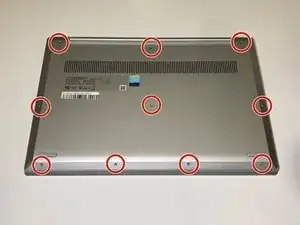
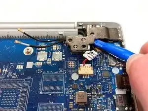
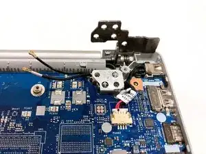
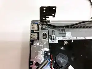
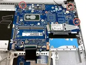

The front center-right screw may be shorter (3.5mm) than the others (6.5mm), and may be captive in the back panel.
Brad Bell -