Introduction

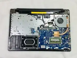
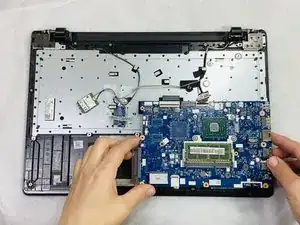
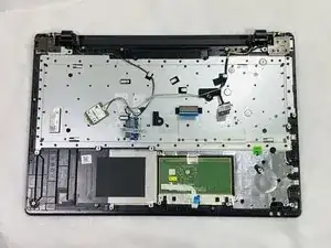
This guide details the steps to remove the motherboard from the Lenovo IdeaPad 110 Touch-15ACL laptop. The motherboard is essentially the heart of the computer and allows the computer to function. The motherboard is a thin-mostly rectangular component that has many wires attached to the other systems within the computer. These wires need to be removed before the motherboard can be removed. The screws which mount the motherboard to the case can be identified by a small white triangle ‘pointing’ to the screw. Exercise caution to mitigate damaging any other internal components and/or damaging the motherboard itself.

Before beginning this repair, be sure to turn off the laptop and disconnect from the power adapter.

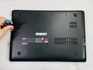
  1. dBcUZSOEKCEEAUIW
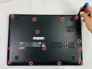
    • Remove the thirteen 6 mm Phillips #0 screws.

  2. PpOAfBBf2sKKCRWo
    PpOAfBBf2sKKCRWo
    JQFLMLKTCdn4hu1l
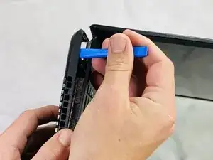
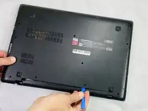
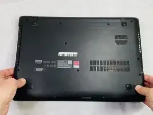
    • Use an opening tool to gently disconnect most of the clips on the back panel.

    • DO NOT force the panel out towards the optical disk drive.

  3. w3xBbxgAZU3cI63P
    w3xBbxgAZU3cI63P
    DbOBLofKM2BXwVAe
    eGeFAVdOlpZwMu6F
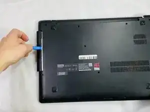
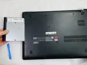
    • Pry the disk drive away from the center of the laptop.

    • Don't worry about any screws since we already removed the screws that are associated with the drive.

    • Once the drive is removed, remove the one 2 mm Phillips #0 screw that is now exposed.

  4. DBNTFlW4rlNFRknw
    DBNTFlW4rlNFRknw
    yKYWaQAT4fFYB2J6
    UHGQUITDFFXMufkR
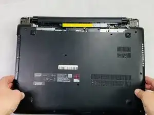
    • Unclip any of the remaining clips and remove the back panel.

  5. XI5Wjcin4ERnnVdS
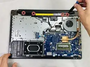
    • Remove the four 6 mm Phillips #0 mounting screws.

  6. DvZKObRlSa5KQvlV
    DvZKObRlSa5KQvlV
    nRXlgpQuB5CmN1dU
    aAM2xukh1BXBWDNN
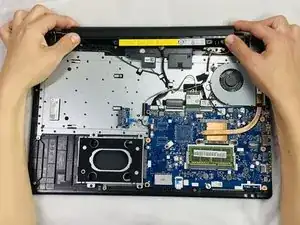
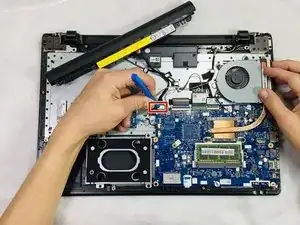
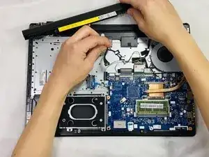
    • Detach the wire connected to the motherboard and remove the battery assembly.

  7. ZLSJKZiI2HZWB2LF
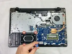
    • Remove the four 4 mm Phillips #0 mounting screws attaching the caddy to the frame.

  8. JfOHBtmIsPrwPeY5
    JfOHBtmIsPrwPeY5
    BtJB2YSxKlYghAxV
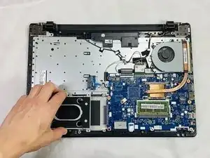
    • Gently remove the caddy away from the motherboard.

    • If you are removing an already existing HDD, unplug the component along with the caddy and remove the four screws mounting the caddy to the HDD.

  9. Q1lRgqbxNmu6f51D
    Q1lRgqbxNmu6f51D
    1PUE2ckvLQyhBGjU
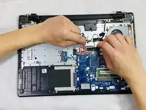
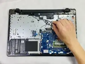
    • Detach the speaker wire from the motherboard.

  10. ReGDHPTxG2KvYR5E
    ReGDHPTxG2KvYR5E
    ISxb5cgtrNlmSZSw
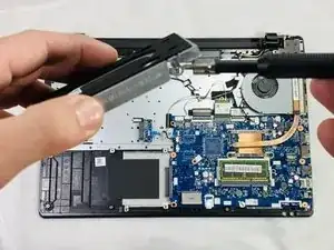
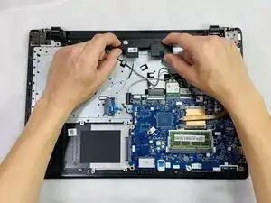
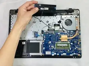
    • Gently pull upwards on the speaker assembly to remove it from the case.

  11. nrIsMBU2jVEEgZFE
    nrIsMBU2jVEEgZFE
    LcZr1W2CLCOSJHip
    qhSDhOUBuMpK64hF
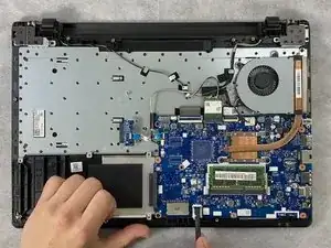
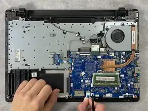
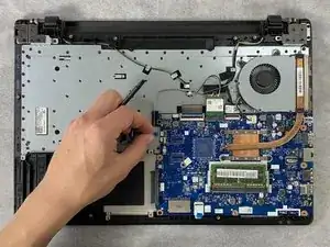
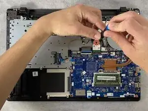
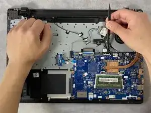
    • Unlock the ZIF connector and remove the wire connected at the bottom of the motherboard.

    • For the wires with the blue plastic, you must undo the clip before pulling out the wire.

  12. QvJoW41m2QDtYa6c
    QvJoW41m2QDtYa6c
    WbhwGMBjmWNb3DYD
    MWN5vE5g6VcXAM3I
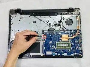
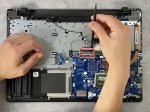
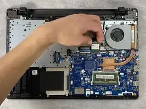
    • Disconnect the wires attached on the "left" side.

    • Use the spudger to unlock the clip to remove the blue ribbon cable.

  13. DHKIIjddfXQuX4NL
    DHKIIjddfXQuX4NL
    YWr3vHkiXphnnDHx
    aR3VE5SDrxHLw4Yt
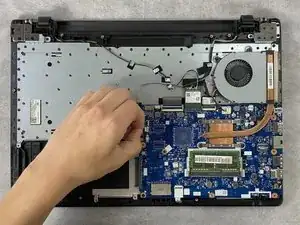
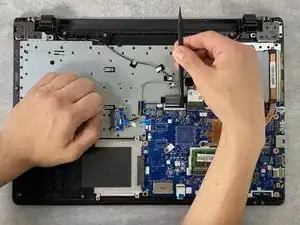
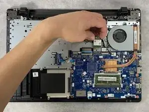
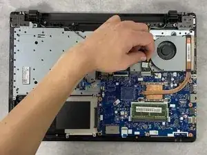
    • Unlock the ZIF connector at the top-left of the motherboard.

    • Remove the ribbon cable.

  14. kYBRRBViCfSqV2yY
    kYBRRBViCfSqV2yY
    FQIYhaT21nOT45cO
    pVvLJZ5YxRDSu1gW
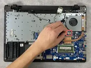
    • Remove the single 4 mm Philips #0 screw from the Wi-Fi card.

    • Slide the Wi-Fi card out of the socket.

  15. jGpKgJFhIV44sMna
    jGpKgJFhIV44sMna
    yhQnbfdgOCyrrUAx
    d3fSwq1ahGotio6J
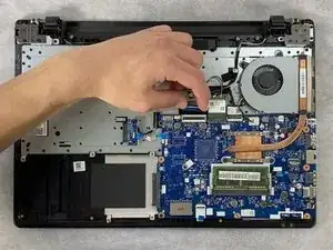
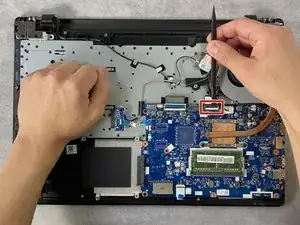
    • Unlock the remaining ZIF connector with a spudger.

    • Remove the ribbon cable.

  16. P5ME3i1CcrHGyIJl
    P5ME3i1CcrHGyIJl
    PTCYqUDArokjSDAv
    BCVTpRZcAdtqtmMo
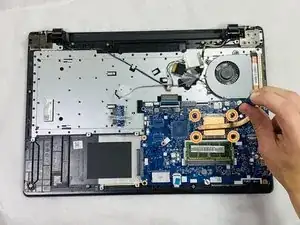
    • Disconnect the fan's wire from the motherboard.

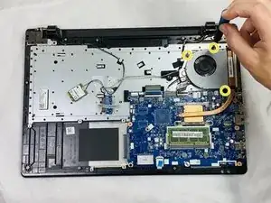
    • Remove the four 3 mm Philips #0 screws joining the heatsink to the motherboard

    • Follow the number order when re-installing.

    • Then, remove the three 5 mm Philips #0 screws holding the fan assembly to the frame.

    • Remove the fan and heatsink.

  17. doDuUOkZQWBfm6tt
    doDuUOkZQWBfm6tt
    IXJvjXJi3loRr1ID
    SOm3BefiPltnSKkV
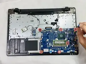
    • Once everything has been disconnected from the motherboard, remove the six 3 mm Philips #0 mounting screws from the motherboard.

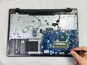
    • There is normally one screw under a sticker at the "bottom" (shown in the picture).

  18. YHiHcGuYIjPBkVNk
    • This is what the frame should look like once everything is removed.

Conclusion

To reassemble your device, follow these instructions in reverse order.
Clark Beuckman

Member since: 22/02/22

529 Reputation

0 comments