Introduction
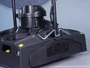
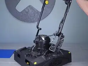
This guide shows how to remove and replace the gear case assembly for the Karcher Rotary Floor Cleaner 17833080 2017.
This guide can also be used to remove and replace the parts listed in the parts section.
-
-
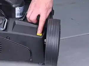
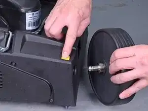
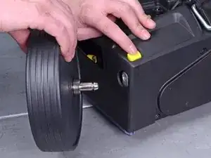
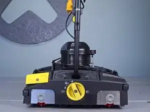
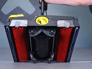
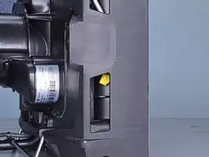
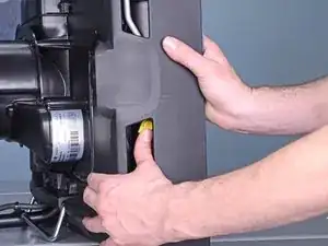
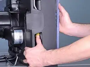
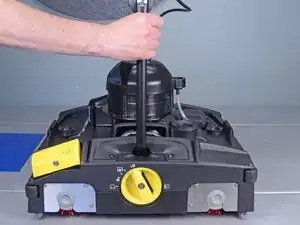
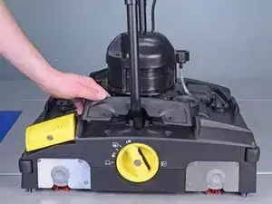
Press the yellow button near each wheel base to release the wheels.
-
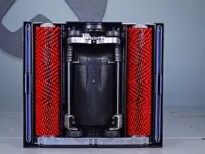
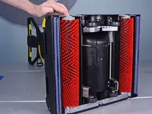
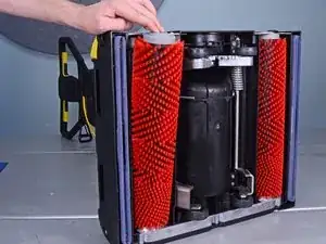
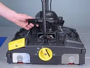
Remove both wheels from their sockets.
-
-
-
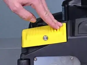
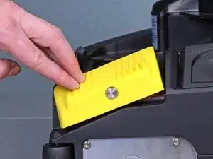
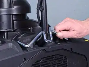
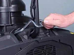
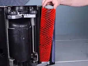
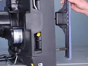
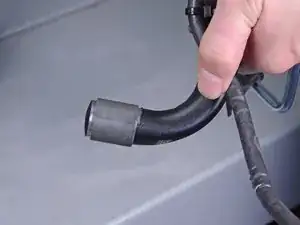
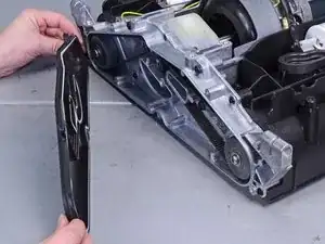
Remove both suction bars.
-
Reassembly tip: When you re-insert the suction bars, be sure to orient the locking tab towards the center of the device. This allows the bars to click in place.
-
-
-
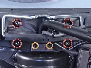
Remove the following screws securing the left retaining bracket:
-
Four T40 screws
-
Two T20 screws
-
-
-
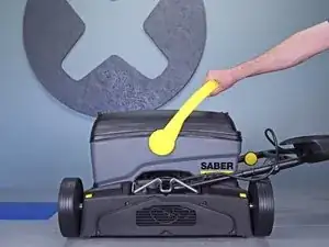
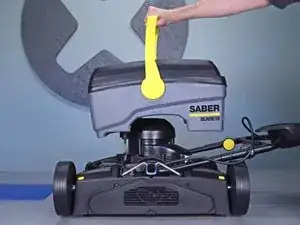
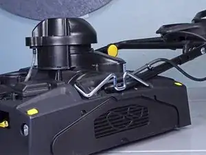
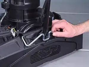
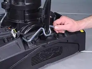
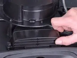
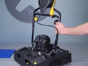
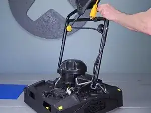
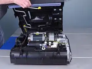
Raise the handle to the upright position.
-
Engage the retaining bracket to lock the handle in place.
-
-
-
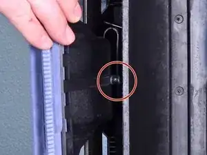
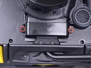
Use a T20 driver to remove the following screws securing the right retaining bracket:
-
Two 85 mm-long screws
-
Four 45 mm-long screws
-
-
-
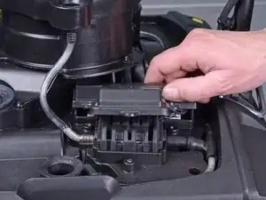
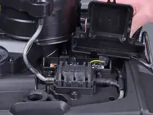
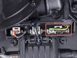
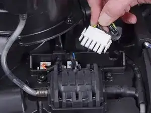
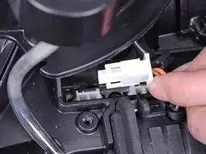
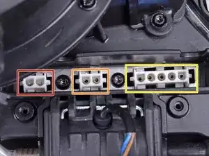
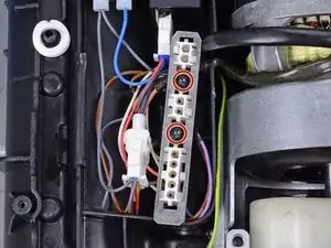
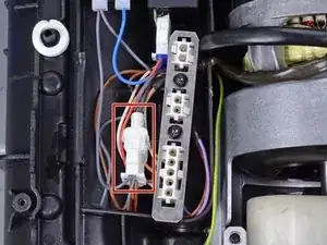
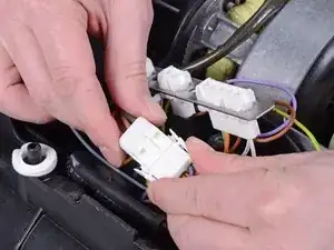
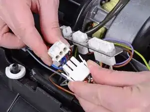
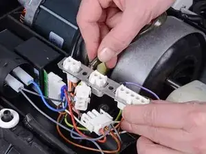
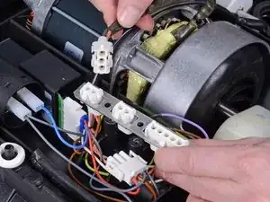
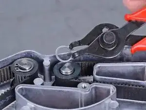
Disconnect the two remaining plugs by squeezing the edges and pulling them out of their sockets.
-
Vacuum motor
-
Pump
-
Handle
-
-
-
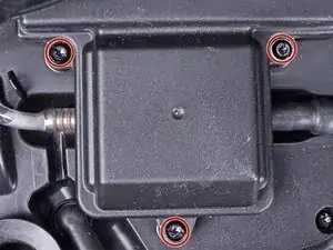
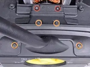
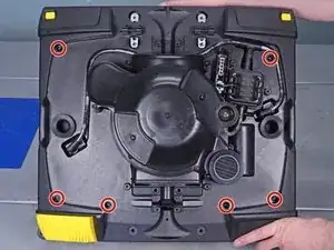
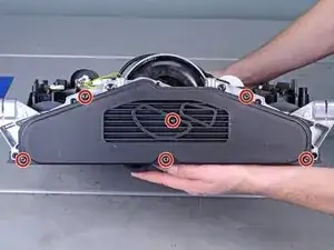
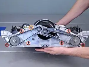
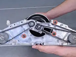
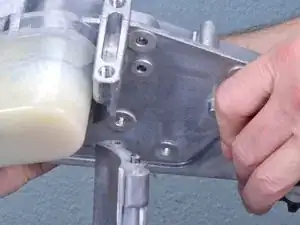
Remove the following bolts from the gear case:
-
Six T20 bolts
-
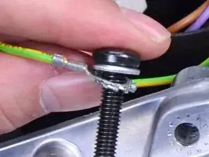
One T30 bolt securing the ground wire
-
-
-
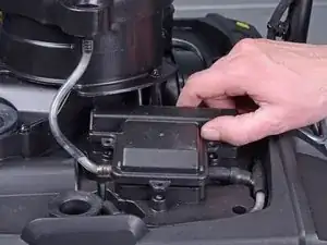
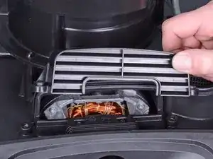
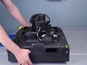
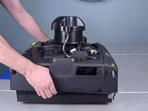
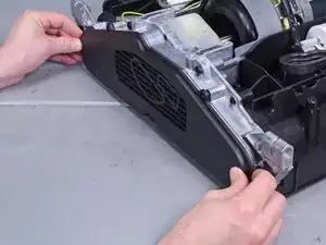
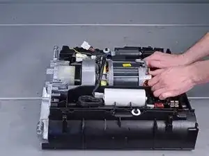
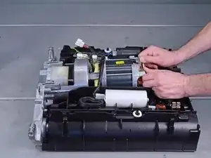
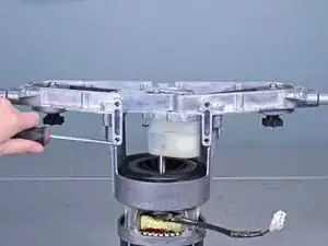
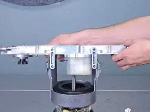
Lift the motor end of the drive assembly up slightly to clear the mounting lip.
-
Push the drive assembly out of its recess.
-
-
-
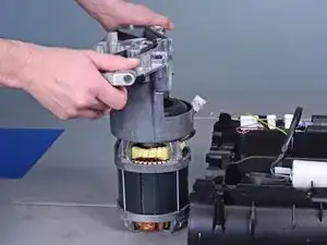
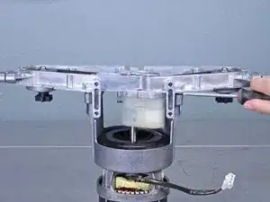
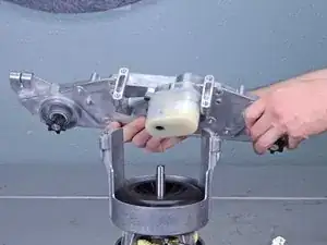
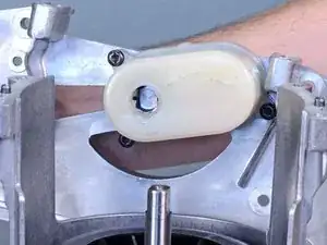
The motor axle is keyed into the gearbox. Rotate the axle until it aligns with the gearbox slot.
-
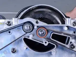
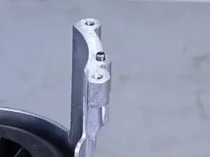
Align the gear case to the motor mount using the two alignment pins.
-
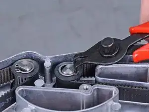
Once everything is aligned, gently tap the gear case onto the motor mount.
-

To reassemble your device, follow these instructions in reverse order.