Introduction

Follow this guide to remove the power switch for the Karcher 15209900 electric pressure washer.

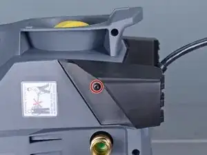
Some of the body screws are deeply recessed and require a T15 driver with a 5-inch long shank in order to reach.

  1. sTyv3aNB2dm4MfO2
    sTyv3aNB2dm4MfO2
    D5ZbsGfh5ZyvgrQ5
    cgc3nZYGHJLUxwK4
    • Before you begin, make sure to power off and unplug the device from the outlet.

    • Unscrew the output hose from the pressure washer.

  2. EBWTJQJvxAIWl2RR
    EBWTJQJvxAIWl2RR
    MHUOdQnUBNgZby1Y
    JJQHjA11NFPhgEhS
    • Unlatch and remove the yellow rubber strap.

  3. WZIEbM5oYdcE2Nr4
    • Use a T20 driver to remove the two 55mm-long screws securing the hand grip.

  4. KieVyE5DudJoAPJB
    KieVyE5DudJoAPJB
    epyU11vLeXSbBtaX
    • Remove the hand grip from the extension bars.

  5. GejtniRRWSLli5wc
    GejtniRRWSLli5wc
    Rgavs3HXQyLABqEX
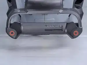
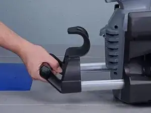
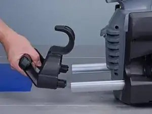
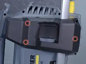
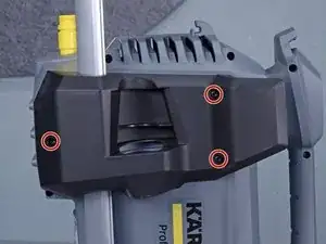
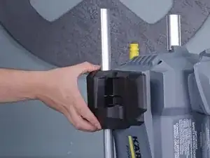
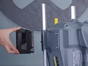
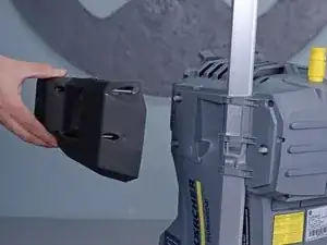
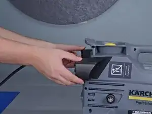
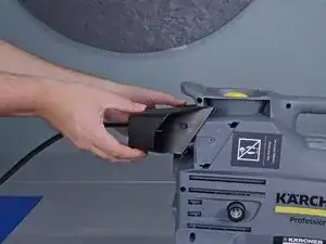
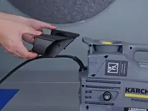
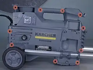
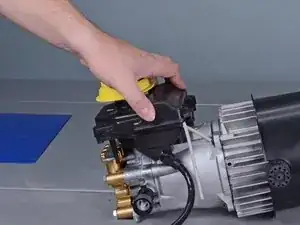
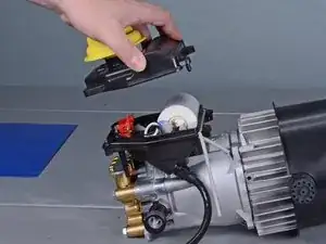
    • Use a T15 driver to remove the six screws securing the top black plastic panels on either side of the device.

  6. Z21nN4HX5GBuiWlc
    Z21nN4HX5GBuiWlc
    CnQr3PdIFhcvZPQc
    YL4amS16wgUWGNVj
    • Remove the two plastic panels.

  7. 4XhUxZhSrZW4HDY4
    4XhUxZhSrZW4HDY4
    uRIaK6tDrcQHtfJb
    • Remove the two T15 screws securing the plastic feet—one screw on either side.

  8. 1OMyUwN3wEnJ3qft
    1OMyUwN3wEnJ3qft
    VJA2KqOF1vRnenSZ
    o66w1MC2IXZO5qoX
    • Unclip and remove the plastic feet.

  9. fkyCtREJdmWQW4gT
    fkyCtREJdmWQW4gT
    bnjfYkiAyFPbUefQ
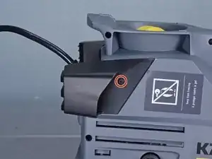
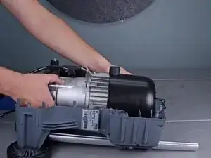
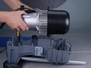
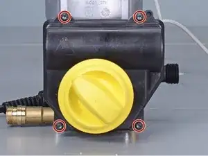
    • Use a T15 driver to remove the ten screws securing the housing halves together.

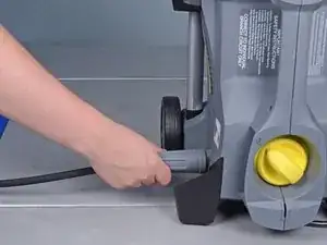
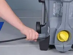
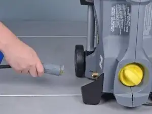
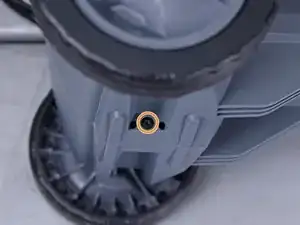
    • Remove the T15 screw underneath the wheel axle.

  10. LGcMqoMCNRqw6Oex
    LGcMqoMCNRqw6Oex
    GRfIFvXqEympLqSO
    • Set the device on its side.

    • Lift the housing half away from the body.

    • If the housing half does not separate, check to make sure you removed all the body screws.

    • Remove the housing.

    • Screws may get stuck inside the plastic housing. Be careful not to lose any screws.

  11. ZwTrKUJiLJvBQjVi
    ZwTrKUJiLJvBQjVi
    kRVq2dtRgsuncNGm
    • Slide the power cord strain relief out its notch on the plastic housing.

  12. XEUfShGY45o5ephH
    XEUfShGY45o5ephH
    5RsBLcA2PuuPlLhm
    • Lift the motor assembly out of the plastic housing and set it aside.

  13. 4KrlWNS4rVPZvNNl
    4KrlWNS4rVPZvNNl
    gPTwA5x1aENRxsPp
    Ab2xCsdeEBTakaAP
    • Reassembly tip: Use these images to help reassemble the housing back around the motor.

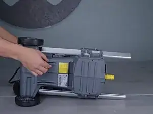
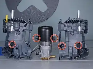
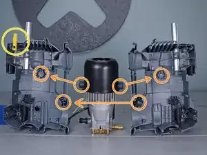
    • Make sure that all five bushings are in place.

    • In order for the housing to fit properly, the bushings must fit in their respective mounts.

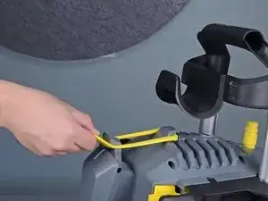
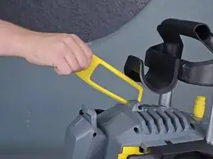
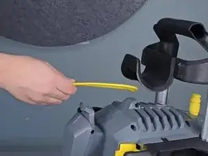
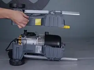
    • Make sure that the yellow tube is properly notched onto the housing.

    • Make sure that the power cord strain relief sits correctly in the housing notch.

  14. iogFPNpjLaD3Jmn1
    • Use a T20 driver to remove the four screws securing the electrical box cover.

  15. w4VaUn2qXJQtXhrR
    w4VaUn2qXJQtXhrR
    KjXGZng2tsCKaQEQ
    • Lift the cover off of the electrical box.

  16. dAElsVu1ABAL2rUK
    dAElsVu1ABAL2rUK
    MkSQ5jDEtbISlqLh
    • Remove the plate spring from the electrical box.

    How to replace back the switch in the box?

    k27b -

  17. NsbeeXQwcWCXLrIu
    NsbeeXQwcWCXLrIu
    VbvBuICJpQYrkUOy
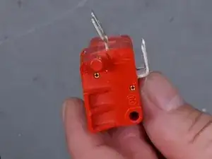
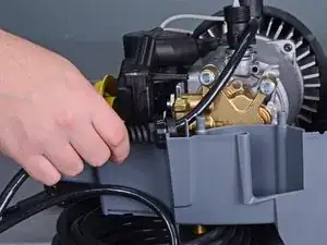
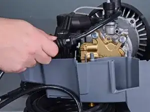
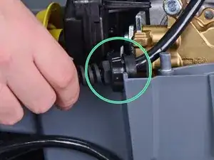
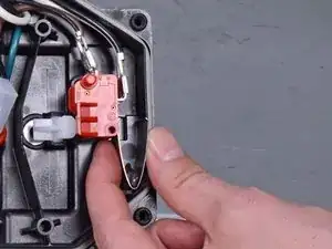
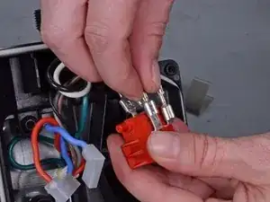
    • Pull the switch out of the electrical box.

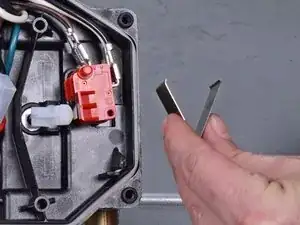
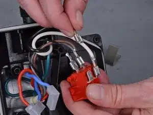
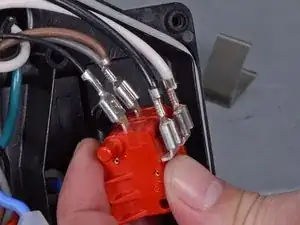
    • Disconnect the four spade connectors from the the switch.

  18. SUfl1MqKP1QnuiER
    SUfl1MqKP1QnuiER
    REFBCqLwBO6rQTOc
    • Remove the switch.

    • Reassembly tip: Use the second photo as a reference to help you properly re-wire the switch.

Conclusion

To reassemble your device, follow these instructions in reverse order.

Arthur Shi

Member since: 03/01/18

248651 Reputation

0 comments