Introduction

The motherboard replacement also replaces the charging port because they come as 1 component.

  1. GhJQoIbNCVS23m6C
    GhJQoIbNCVS23m6C
    HQtJv5BXnYfeGPK1
    WLYiYaRQMwUu6Akv
    • Before working on the device, make sure the device is off and not plugged into any power source for safety reasons. Failure to comply could result in injury.

    • Place the device on a firm surface with the device screen facing down.

  2. 6Mudg4HcDSTxhOBX
    6Mudg4HcDSTxhOBX
    vHPxINmpN3ZSRSPi
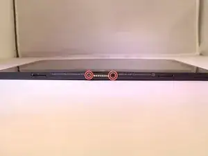
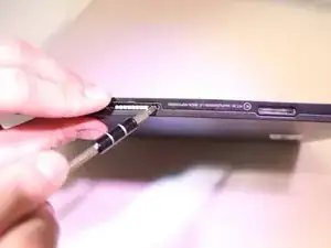
    • Remove 2, 6.1 mm Phillips J000 screws from the back of the device.

    • If any screws are stripped, refer to the ifixit guide for how to remove a stripped screw. How to Remove a Stripped Screw

    I just checked and there are no screw holes on my Insignia 11.6” tablet!

    Mugsys RapSheet -

  3. Im3eqAXndT4QjKnn
    Im3eqAXndT4QjKnn
    WaDHvRxZKVCuCKAB
    3s3RGwQQFQ64IN36
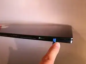
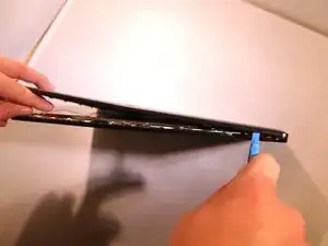
    • Using a plastic tool and the plastic card, gently pry off the back cover.

    How many locking tabs are there? I see one in the corner.

    Mugsys RapSheet -

  4. KJKOp6m1tiL3kBpM
    KJKOp6m1tiL3kBpM
    OQPu315rJWCiWaWB
    oJSaTIWqXuuVPVu4
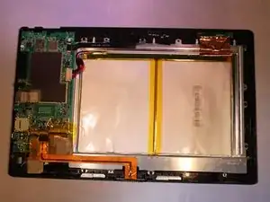
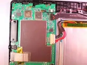
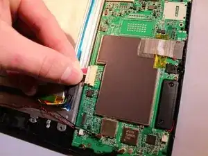
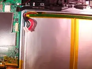
    • Using tweezers, remove the electrical connector that connects to the battery to remove the power to the battery.

  5. PBJYhAIujBpHG2b6
    • Unplug the 2 speaker's connection from the motherboard.

  6. kVZxe6a5OXNNUuux
    kVZxe6a5OXNNUuux
    dpr5iXXVwmYDF1tZ
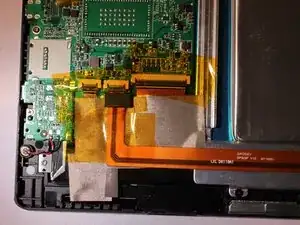
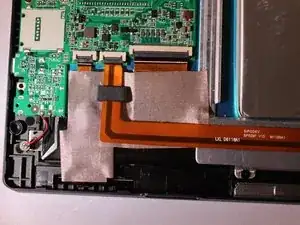
    • Peel the yellow tape off from on top of the electrical connectors.

  7. 4n2YAIcnQGIaGASp
    4n2YAIcnQGIaGASp
    oHTjUNWIryMjsYtr
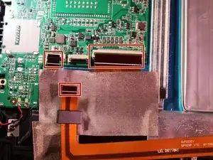
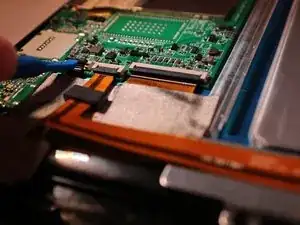
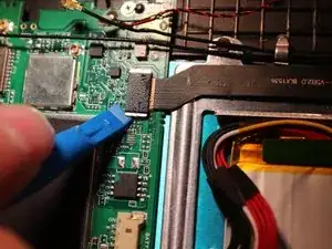
    • Flip up the black cover pieces to expose the 3 electrical connectors.

    • Remove 3 electrical connectors by gently pulling back on them with some tweezers.

  8. ftsHhRjOEPD1mMME
    ftsHhRjOEPD1mMME
    HG4qYtg1DsDwLKAJ
    XR3hRsSLqYEFS1TO
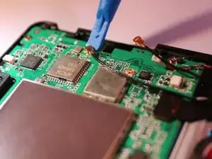
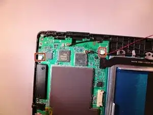
    • Unplug the 2 black ground wires from the motherboard by gently prying on them until they unhook from the motherboard.

    • Remove the black camera connector by gently prying on it until it unhooks.

  9. rJOeKLiBENRoxlgF
    rJOeKLiBENRoxlgF
    OdCApTxFdb3JkrxB
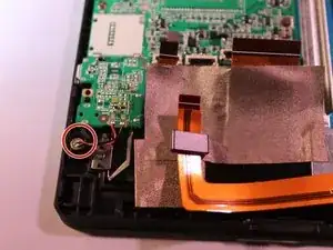
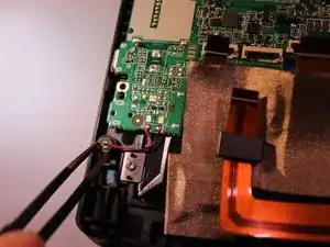
    • Using tweezers, remove the microphone from the the plastic cover.

  10. UOkfkbaYkpIEY3Ld
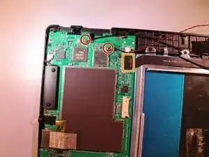
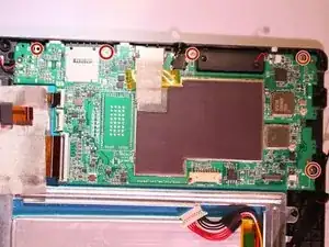
    • Remove 5 - 3.4 mm Phillips J000 screws from the motherboard.

    • Motherboard pops out.

Conclusion

To reassemble your device, follow these instructions in reverse order.

Connor Sweeney

Member since: 28/09/16

449 Reputation

2 comments

This looks great. Can you provide more detail on Step 3 (opening the case?) Are there locking tabs that I need to worry about breaking? And if so, how many? Does the cover simply snap back into place?

I need to open my unit simply to disconnect the power to clear the BIOS. I stupidly disabled my USB ports and there is no way to navigate the BIOS without the (USB) keyboard (how freaking dumb is that!)

Mugsys RapSheet -

Very nicely done. Do you suppose that the SSD can be upgraded to something larger?
Curtiss Riedel -