Introduction
Tools
-
-
Position the tablet with the top edge by the camera facing down.
-
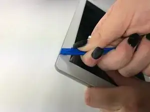
Insert the plastic opening tool between the front panel and back case at the upper left hand corner of the tablet.
-
-
-
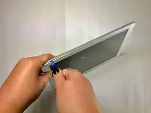
Slide the plastic opening tool along the edge of the tablet between the front panel and back case.
-
Repeat this process for the two shorter edges of the tablet leaving the top edge by the camera still snapped in place.
-
-
-
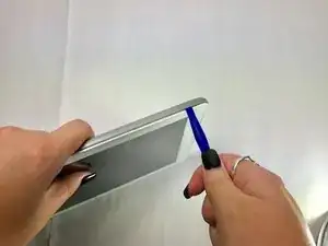
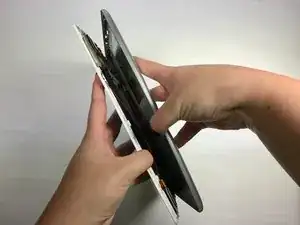
Using an unfolding motion along the top edge of the tablet, carefully separate the front panel from the back case.
-
-
-
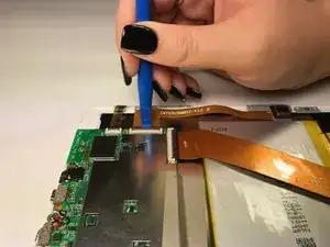
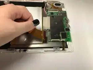
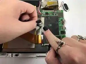
Using the plastic opening tool, lift up the black retaining flap that secures the camera ZIF (zero insertion force) ribbon connector to the motherboard
-
-
-
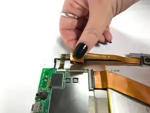
Pull the ZIF (zero insertion force) ribbon connector out from underneath the black retaining flap.
-
-
-
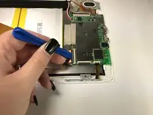
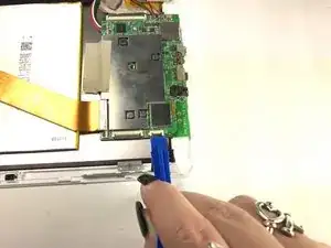
Using the plastic opening tool, lift up the black retaining flap that secures the ZIF (zero insertion force) ribbon connector over the battery to the motherboard.
-
-
-
Pull the ZIF (zero insertion force) ribbon connector out from underneath the black retaining flap.
-
-
-
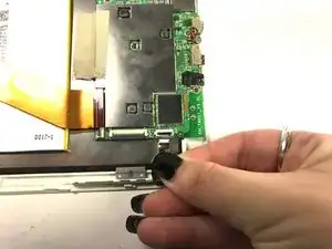
Using the plastic opening tool, lift up the black retaining flap that secures the volume and power button ZIF (zero insertion force) ribbon connector to the motherboard.
-
-
-
Pull the ZIF (zero insertion force) ribbon connector out from underneath the black retaining flap.
-
-
-
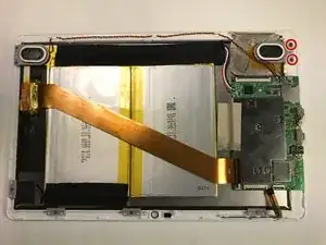
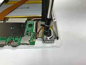
Using the Phillips #000 screw driver, unscrew the two 4 mm screws securing the right speaker to the front panel in a counterclockwise direction.
-
-
-
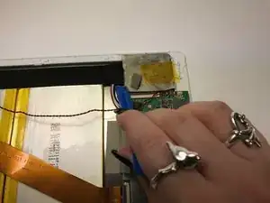
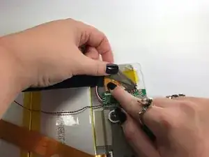
Using the plastic opening tool, remove the silver tape covering the display ZIF (zero insertion force) ribbon connector.
-
-
-
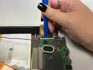
Using the plastic opening tool, lift up the black retaining flap that secures the display ZIF (zero insertion force) ribbon connector to the motherboard.
-
-
-
Pull the ZIF (zero insertion force) ribbon connector out from underneath the black retaining flap.
-
-
-
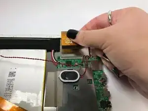
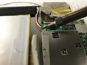
Desolder the four joints connecting the red and black wires from the speakers to the motherboard.
-
-
-
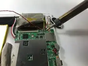
Desolder the three joints connecting the red, black, and white wires from the battery to the motherboard.
-
-
-
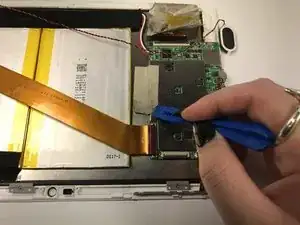
Using the plastic opening tool, remove the silver tape that secures the motherboard to the front panel.
-
-
-
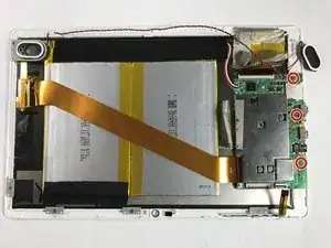
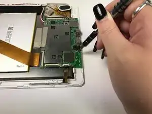
Using the Phillips #000 screw driver, unscrew the three 4 mm screws securing the motherboard to the front panel in a counterclockwise direction.
-
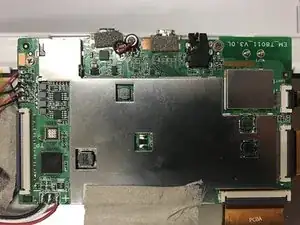
The motherboard is now free from the device and can now be replaced. To reassemble your device, follow these instructions in reverse order.
One comment
где можно приобрести такую плату
