Introduction
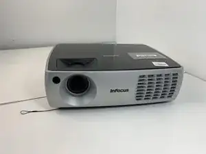
This Metal Cover needs to be removed in order to replace most parts in the device.
Tools
-
-
Turn the projector so that the lens is facing you.
-
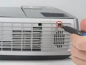
Use a Phillips #1 screwdriver to remove the 6 mm screw that secures top cover.
-
Remove the service cover.
-
-
-
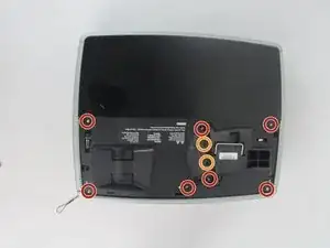
Use a Phillips #1 screwdriver to remove the seven 6 mm screws.
-
Use a Phillips #1 screwdriver to remove the two 5 mm screws.
-
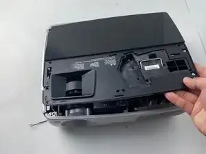
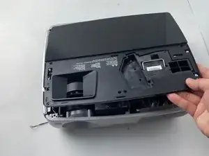
Remove the top cover.
-
-
-
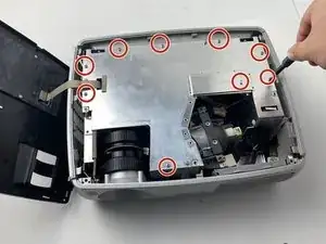
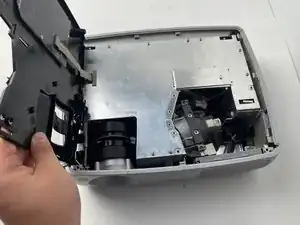
Use a Phillips #1 screwdriver to remove the nine 6 mm screws.
-
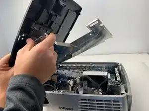
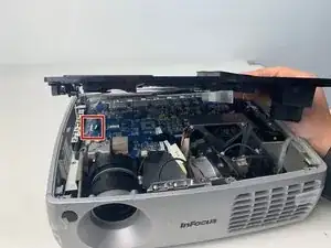
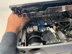
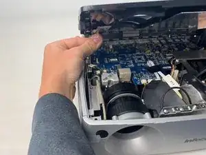
Lift up the metal cover and set it aside to reveal the motherboard.
-
-
-
Carefully pry up the black plastic locking bar of the ZIF connector on the motherboard with a plastic spudger.
-
Pull out the blue-tipped, white ribbon cable from the connector.
-
Remove the metal cover.
-
To reassemble your device, follow these instructions in reverse order.
