Introduction

Ethernet cables are widely used to connect devices to networks, and ensuring their continuity is essential for maintaining a reliable connection.

Continuity testing is a simple process that can help you detect any faults or breaks in the cable that may be causing connectivity issues.

  1. q5CIVqSmTnOILC2Y
    q5CIVqSmTnOILC2Y
    CYFCblPqIYJsICaT
    • The tester has two ports on each part:

    • RJ11 (6P2C)

    • RJ45 (8P8C)

  2. DUtSJgFGB4RrODUI
    • Connect one end of the cable on one half of the tester each.

    • If you are testing jacks you can just connect them with a known good patch cable.

    • If the other side of your cable is already connected to a switch or some other device you can connect the MASTER device only.

    • Only do this with cable testers you trust, since crappy cable testers might not limit the current they send through the data lines.

  3. EfniQUjBsJCxXTEY
    • Switch on the tester.

    • The tester has two modes: ON and S. There is no difference in the two modes besides the testing interval on S being more drawn out.

  4. tOQSCVgMWqaNnNjv
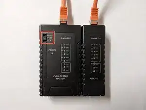
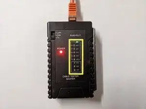
    • The tester will go through all the wires in sequence. If the sequence of the green lights blinking does not line up you might have swapped some wires when wiring the connector.

    • If some lights do not light up there might be a break in the cable or you made a mistake when crimping the connector.

    • For Fast Ethernet (100 Mbit/s) you only need pins 1, 2, 3 and 6. Some cheap cables may not even have more than these four wires.

    • G means ground. For most consumer applications up to 1GbE it should be fine if your ground is not properly connected.

Conclusion

Good luck on your next project!

Sebastian

Member since: 19/08/18

19300 Reputation

0 comments