Introduction
An Audio/Visual port enables a device to send or receive sounds and images. If these are not coming through, the A/V port may be at fault. If the A/V port is determined to be faulty, this guide will demonstrate how to replace the A/V port in the Konica Minolta DiMAGE Z3. This repair is not only relatively expeditious, but also relatively easy, and requires no major technical skills to complete.
-
-
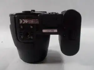
Open the battery chamber door by sliding the door to the side of the camera to release the safety catch.
-
Lift the door up to open.
-
-
-
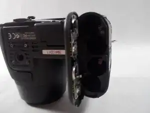
Insert the four batteries inside of the battery chamber door.
-
Make sure the positive and negative battery terminals are in the correct position.
-
-
-
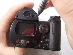
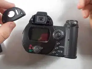
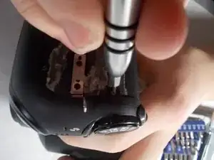
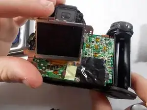
Remove the screen cover by applying slight pressure at the top, then pulling the screen protector away from the camera.
-
-
-
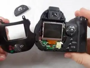
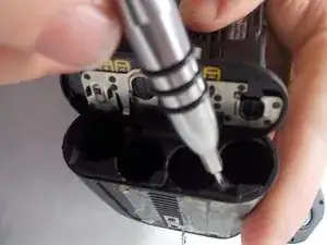
Pull the wrist strap away from the front of the camera to remove it.
-
Then carefully pull the back casing apart from the camera.
-
-
-
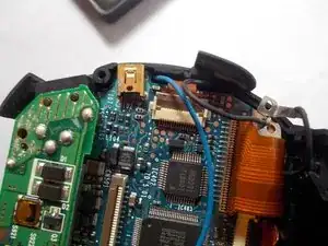
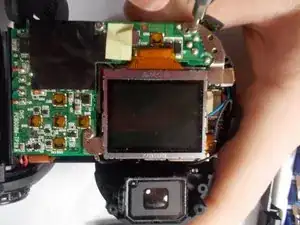
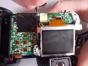
Use tweezers to carefully pull the ribbon cable from the circuit board, not from the LCD screen.
-
Peel back tape on LCD screen to reveal where the wires are attached. Use tweezers to detach the wires from the LCD screen.
-
-
-
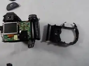
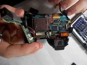
Carefully remove the circuit board from the motherboard.
-
Leave the wires attached to the circuit board.
-
-
-
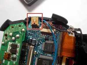
The A/V port is glued to the motherboard. Heat should be applied carefully with a heat gun to loosen the adhesive.
-
Remove the A/V port with a spudger.
-


To reassemble the device, follow these instructions in reverse order.
One comment
Thanks for the help that enabled me to disassembling a Z5.
Is not exactly the same, but helped a lot.
I post comments about the differences I found.
I want only to reack the cursor buttons.
Regards
Joaquim
Joaquim -
Is it correct “insert” the batteries?
It is not advisable to take them out !
Any how, I was able to reach the cursor left button, on a Dimage Z5, that is not working. It looks like the problem is on the mechanicall button and not on the switch itself.
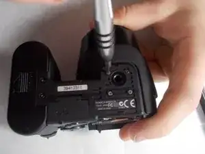
There are small differences, between Z3 and Z5, concerning disassembling, mainly a screw, longer than the others, close to the USB port.
So, thanks a lot for the help you gave to me.
Júio
Joaquim -