Introduction
Sometimes the moving about of computer speakers leads to broken wires and the speakers will fail to work properly. This guide will show you how to repair a Harman Kardon CN-04N567-48220 external computer speaker.
Tools
-
-
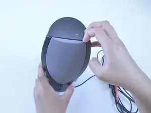
Use your fingers to pull the top of the speaker grill away from the speaker enclosure.
-
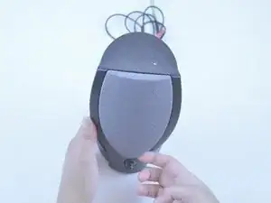
Pull the bottom of the grill away from the speaker enclosure and then completely remove the grill.
-
-
-
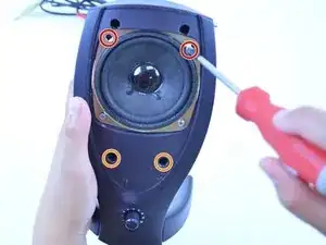
Remove the top two 9.5 mm Phillips #1 screws from the speaker.
-
Remove the two 9.5 mm Phillips #1 screws located below the speaker screws.
-
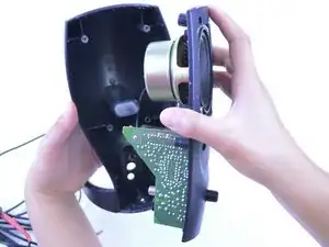
Slowly work your way around the seam until the two parts of the enclosure are free.
-
-
-
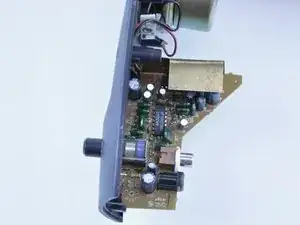
Inspect both sides of the printed circuit board (PCB) for any raised traces, off-colored areas, or loose components.
-
-
-
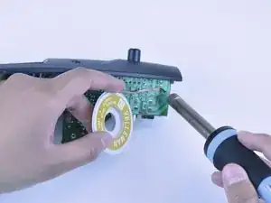
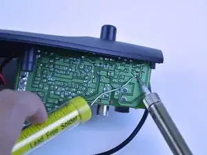
Use desoldering braid and a soldering iron to wick away the old solder and wire remnants from the solder pads and through-holes.
-
-
-
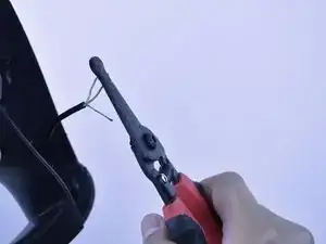
Use wire strippers to remove a small section of insulation from the wires.
-
Use a soldering iron and solder to tin the wires. This prevents the strands from fraying.
-
-
-
Insert the yellow wire into the through-hole marked "R".
-
Insert the bare ground wire into the through-hole marked "G".
-
Insert the white wire into the through-hole marked "L".
-
-
-
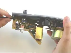
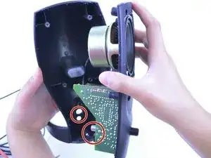
Reassemble the two parts of the enclosure making sure that the PCB-mounted audio jacks are lined up with the mating holes of the rear enclosure.
-
To reassemble your device, follow these instructions in reverse order.
