Introduction
Issue: My metering mode button (To change from Matrix, Spotlight, Centre-Weighed, or Spot Metering) stopped working.
It could still be changed using a Tethering software, but didn’t want to have to lug a laptop to just change it. I could program buttons for doing individual modes, but there was no way to replace another button with that functionality.
Sometimes hitting it just right had it working correctly, but that didn’t work.
It had been sent in to Nikon for service, but they returned it with “No Fault Found” and they had cleaned it, replaced the grip rubber… which was a lie; the disassembly, clean, and then reassembly fixed the issue. This took about 8 weeks, and about $300 (as it was out of warranty).
That the issue returned pissed me off enough that was going to do the repair myself. I had found one person with some videos of opening it up, but had not been able to find anything (nor anything on this site…).
I didn’t think at the time to capture pictures, and don’t feel like opening up the camera again! If I need to do so in the future, I will definitely do so, or if I can get my hands on a broken D500.
Note: I have had to do these steps several times, as the connector has not stayed in the right spot for some reason. I have used some Polyimide Tape this time to try to prevent it from moving, as it has been well over a year since I last had to deal with it.
-
-
Remove the Memory Card(s) from the camera
-
Remove the Battery from the Camera, and close the battery compartment cover
-
-
-
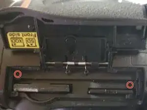
Remove the 2 screws beside the memory slots, then close the cover.
-
Note: make sure to remove the memory cards first!
-
-
-
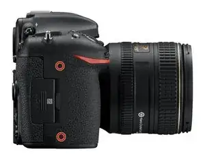
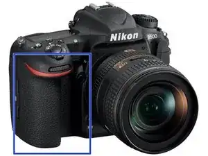
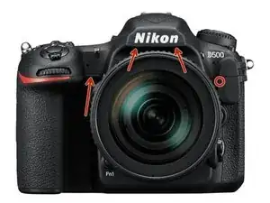
Remove the 2 screws under the rubber grip part by peeling back the rubber grip
-
Try not to damage the double sided adhesive under the rubber.
-
-
-
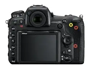
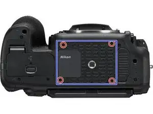
Remove the 2 screws under the rubber pad marked in red.
-
Try not to damage the double-sided adhesive under the rubber.
-
Note: There is a 3rd screw under the flap, which holds the back to the top (marked in yellow). If needing to remove the back panel not just the memory cover flap, it can be removed at this time as well.
-
-
-
Lift out the assembly panel, it should come free without much force.
-
May open the panel to release it.
-
-
-
Carefully pull the back plate off the camera
-
There are 2 ribbon cables that need to be disconnected from the main board to free the rear panel from the camera.
-
To release the cables by flipping up the tap on the side away from the cable
-
When reconnecting the cables, make sure the cables are fully seated before flipping the latch back down.
-
The black cable goes to the LCD (on the tilt screen), the other one goes to the buttons.
-
The LCD cable does have less slack, so is easier to release first, and reconnect last.
-
-
-
Carefully remove the Rubber grip from the camera
-
Careful to not damage the double-sided adhesive
-
-
-
Carefully remove the Rubber grip from the camera
-
Careful to not damage the double-sided adhesive
-
-
-
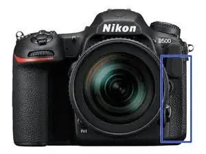
Remove the diopter cap from the end of the diopter (use a flat head or pry tool)
-
Un-screw the phillips screw from the diopter
-
When reconnecting, make sure the cap is seated in correctly and the double sided tape is not damaged (or replace)
-
There is a notch which the indicator has to seat into, or it will not sit down correctly when it is reinstalled.
-
-
-
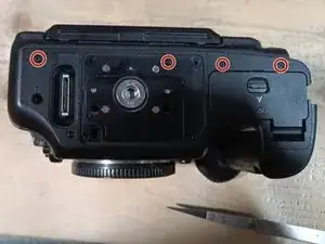
Remove the screw under the top assembly, had been hidden by the grip.
-
Remove the 2 screws from the bottom of the mirror box
-
Remove the lens or lenscap prior to doing this step to gain access, then reattach.
-
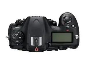
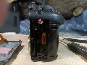
Remove the screw from beside the accessory socket
-
-
-
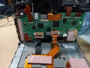
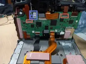
Disconnect the 2 ribbon cables from the main board (Red boxes)
-
Lift the black tabs above the cables to release the cables
-
When reseating the cables, make sure they are fully seated before closing the locking tab
-
Disconnect the wifi sub-board with the wifi cable from the main board (Blue Box) or gently disconnect the wifi antenna (Blue circle)
-
-
-
Carefully lift the top assembly free.
-
Note, there is a thermal pad on the left hand side, almost right under where the strap lug is. Red Box. Careful to not damage it.
-
-
-
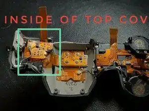
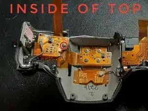
Once the top assembly is disconnected from the rest of the camera, the area for the service is highlighted in the green.
-
Connect an anti-static strap to the magnesium shell, making sure it touches some unpainted part, to make sure you don't damage any components.
-
(This picture came from an ebay part listing)
-
-
-
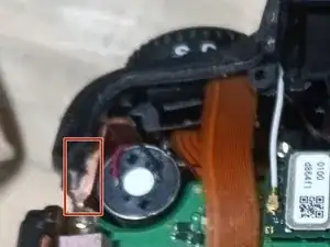
Carefully remove the retaining screw that secures the soft ribbon cable that has components on it.
-
Careful to not damage the part in any way, as may break traces.
-
-
-
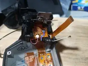
Once unfolded, Locate the white socket with the tiny ribbon cable (it's about about 4 mm wide), cable highlighted with blue
-
-
-
Using tweezers, gently release the latch part of the socket. The latch is on the side away from the socket
-
Release the wiring harness from the socket, careful to not damage it.
-
-
-
Inspect the end of the connector for any corrosion, remediating if any is found.
-
Reseat harness in the connector gently, using tweezers. Make sure the cable is correctly seated and seated correctly.
-
Engage the latch holding the harness into place.
-
-
-
I use a tiny bit of tape to help keep the harness from moving at all. This would be optional, as if it's still under warranty, would make it obvious someone had opened the camera up.
-
-
-
(Sorry, do not have an image for this step)
-
Fold the flex cable back up, and secure with the screw, careful to not over tighten.
-


To reassemble the camera, follow the Prerequisite guides in reverse order.
- Make sure all ribbon cables are fully seated before closing the latch, or the camera may not work correctly
- Make sure the camera is fully functional, to confirm all the parts were connected correctly.
- Many screws are into plastic, make sure to not over-tighten them