Introduction
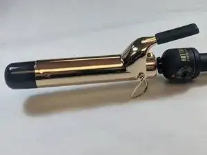
Below we have outlined a few issues that we plan to address based on the research that we have conducted.
- Heating coil burn out
- Temperature control switch burn out
- On/Off switch burn out
Tools
-
-
Ensure that you have a clean work station, and that you can easily keep track of small, loose parts.
-
In addition, MAKE SURE IT IS UNPLUGGED FOR ALL FOLLOWING STEPS!
-
-
-
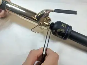
Firmly grasp the end of the Iron with the black plastic cap on the heating element end.
-
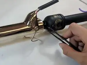
With your free hand, use tweezers to firmly grasp the small retaining ring sitting between the heating element and the handle body.
-
Once you have a firm grasp, pull up on the retaining ring, and it should come loose.
-
-
-
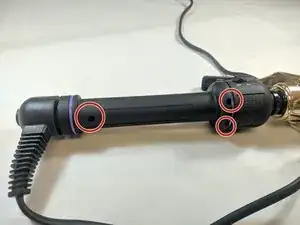
With the ring loose, turn the handle body over, and you will see three screw holes.
-
Take a PH1 screwdriver, and loosen up all three 6mm Phillips #1 screws in the handle body.
-
-
-
Once the screws have been removed, set them aside and with a pry tool, firmly pull the handle body apart in half lengthwise.
-
-
-
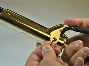
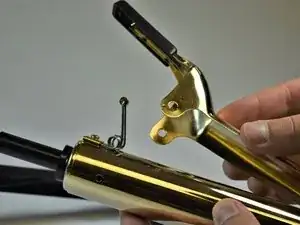
For removing the clamping mechanism, firmly grasp the iron in your hand by the handle body, and locate the screw as shown in the picture.
-
Remove the screw shown (8mm Phillips #2 Pan Head) and when finished do the same for the opposite side.
-
-
-
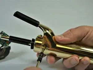
Once both screws have been removed, continue to remove the top clamping half of the mechanism from the body of the Iron.
-
-
-
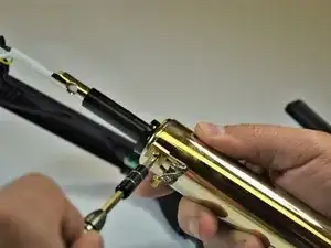
Rotate the handle, and remove the screw that holds on the spring mechanism for the clamp. This screw is a 8mm Phillips #2 Pan Head.
-
Once this step is fished your Hot Tools Professional 1110 will be fully disassembled and ready to have its components replaced.
-
-
-
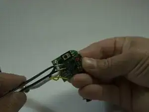
Remove the board gently from its location. Note how its shape fits its location for easy assembling.
-
-
-
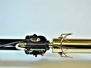
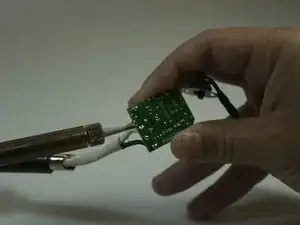
The white cable is the heating coil. It is powered through the board by the power switch. It has three small wires that are soldered on the board.
-
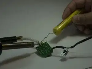
Desolder the three wires as shown on the picture. Mark the location of each wire.
-
Refer to Hot Tools Professional 1110 Power Switch Replacement for more guidelines.
-
To reassemble your device, follow these instructions in reverse order.
