Introduction

This guide shows how to remove and replace the oil level switch for the Honda EU2200IT generator. The switch is attached from within the crankcase and requires major disassembly.
If you encounter problems during the process, consult the official Honda service guides.

Drain the fuel from the fuel tank before you begin this procedure. Any fuel remaining in the tank will spill out. Be ready to contain any spillage.

The crankcase must be resealed with liquid sealant. Be sure to have Threebond 1207B or equivalent liquid sealant at hand before you begin the procedure.

You will need to refill the engine oil for this procedure. The generator requires up to 0.46 liters of SAE 10W-30 oil.

You may find it helpful to loosely replace the bolts after you removed a part, in order to keep track of the bolts and to keep the screw holes clean.

  1. 2RcWcdXnpuMICOPf
    • Before you begin, make sure the generator is switched off and the generator is cool to the touch.

  2. 4pUWZSMoPDsUsmgB
    4pUWZSMoPDsUsmgB
    ovqPPHBsYDOyPTWB
    • Lift and remove the spark plug cover.

  3. LBekvfGNewVuFSmt
    LBekvfGNewVuFSmt
    GSUCKM2i6mTB6bAt
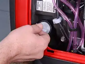
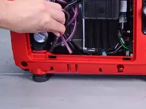
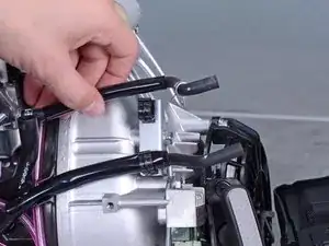
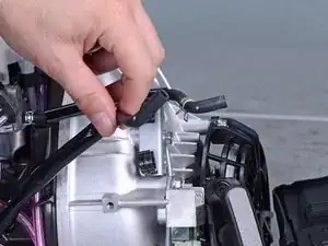
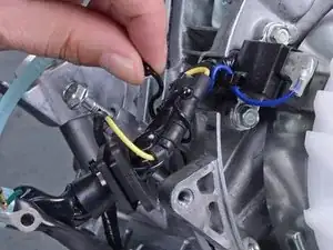
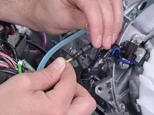
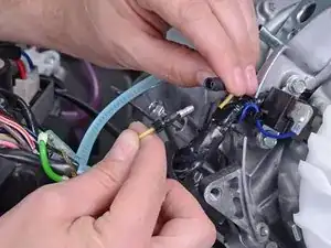
    • Grab the plastic housing at the end of the spark plug wire.

    • Pull firmly to disconnect the wire from the spark plug.

  4. OHs3UlmVblBpcMIe
    • Use a Phillips #2 screwdriver to loosen the screw holding the maintenance cover in place.

  5. aTiAjAVTQqrOBmJd
    aTiAjAVTQqrOBmJd
    3FVmFTPjDxllE1XA
    qWOoL4xyWLOLq3vO
    • Swing the top of the maintenance cover out.

    • Remove the maintenance cover.

  6. 6dyxXaqnwLNMTxdR
    6dyxXaqnwLNMTxdR
    3cxmFoMqPHLX6TBj
    • Unscrew and remove the oil filler cap.

  7. RACSGqrK6SIjYqaP
    RACSGqrK6SIjYqaP
    MDLqFiZsmpfKVJrp
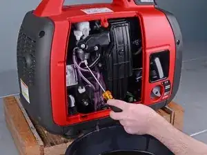
    • Place an oil pan below the fill port to catch the engine oil.

    • Carefully tilt the generator towards the oil pan to drain the oil.

  8. RlqldmCjgs5iDnk1
    • During reassembly, be sure to refill the engine oil:

    • If you recently resealed the crankcase cover with liquid sealant, wait at least 20 minutes before adding oil.

    • Use SAE 10W-30 oil, up to 0.46 US quarts.

    • Add oil until the dipstick is almost completely submerged.

  9. rCRtpZgEfZdmC5tx
    • Place a container below the drain tube to catch the excess fuel.

  10. wxYRcebFImr13IjY
    wxYRcebFImr13IjY
    PEUoaVDsOEBY4xi6
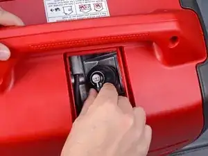
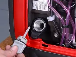
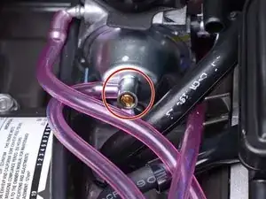
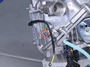
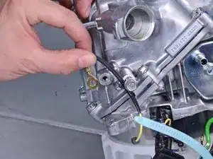
    • The carburetor drain screw is located at the bottom of the carburetor.

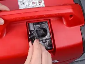
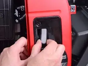
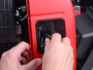
    • Use a flathead screwdriver to loosen the fuel drain screw until fuel begins to drain out of the carburetor.

    • Once you drain the fuel bowl, re-tighten the fuel drain screw.

  11. IevjIFofarTfuvKQ
    • Remove the four Phillips screws securing the back cover.

  12. KMXm1ijxBJAWeUD4
    KMXm1ijxBJAWeUD4
    DGHwl5y2ljKY6Ujj
    • Remove the back cover.

  13. HyIrb2ArJUb5NjKG
    HyIrb2ArJUb5NjKG
    IBTJdOH6EIP3HZ5c
    wBLuJX2JCTnTij4g
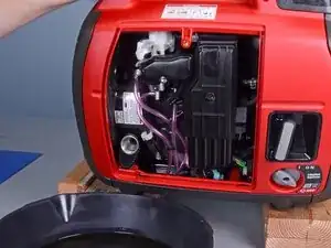
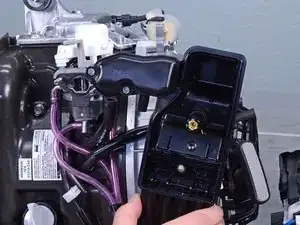
    • Remove the four screws securing the front cover:

    • Two Phillips screws

    • Two Phillips screws (one on each side)

  14. E4YIHqPvwJ5SYBFb
    E4YIHqPvwJ5SYBFb
    A6uXJuEgTJBExTfM
    LAaDjT6hlXHhkTWo
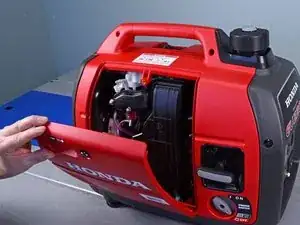
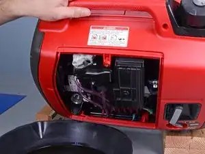
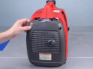
    • Swing the top edge of the front cover away from the generator.

    • Pull the front cover away slightly away.

    • The front cover still has many wires connected to it. Be careful not to strain any wires.

    This cover was damaged upon arrival. How do I take it off completely to replace it.

    janeenerider -

  15. vqHIagLNaW6o5AqO
    vqHIagLNaW6o5AqO
    XMebgsjusLhvX2GD
    YRZgPUwCTLoUiUDF
    • Remove the lower gray plates from both sides of the generator.

    • During reassembly, be sure to reinstall the gray plate with the air vent cutout onto the right (access-side) cover.

  16. uCUIuVHSQXx3pEOC
    uCUIuVHSQXx3pEOC
    vauBiWyQRQCqloXu
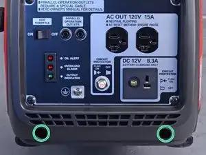
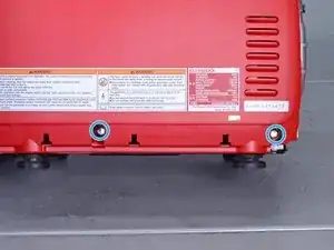
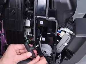
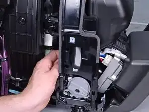
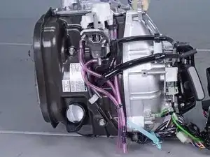
    • Remove the fasteners securing the left (non-access) cover:

    • Two Phillips screws

    • Two 10 mm bolts

  17. UttIwgybVZRUPHrn
    UttIwgybVZRUPHrn
    a1lk4affRvLxRrkg
    • Remove the left (non-access) cover.

  18. ACOdPmRP4KHOtEZ5
    ACOdPmRP4KHOtEZ5
    KBPkFyceDyYbMITZ
    UqWNagNIELEOE15R
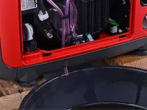
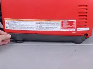
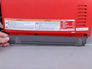
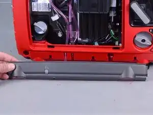
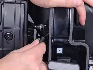
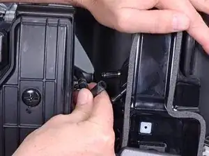
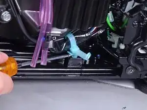
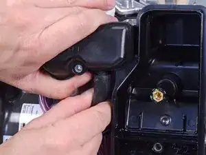
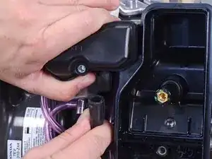
    • Slide the vent and drain tubes out of their cover ports along the bottom of the right cover.

  19. PFpEl1YrodUoNTfN
    • Remove the Phillips screw securing the starter rope port.

  20. xZcHWRSU4vpmqssV
    xZcHWRSU4vpmqssV
    VsYbraECvkfTnF1W
    • Thread the starter rope handle through the port's cutout.

  21. ukPOeKloWKofj5A4
    ukPOeKloWKofj5A4
    WyKrVtkP4Rmu3xdk
    • Remove the right (access-side) cover.

  22. bLJieCn4NDevLWqB
    bLJieCn4NDevLWqB
    3G4xHVFsgMwG3yD2
    p4OWLMdkEGQMYpfZ
    • If you are replacing only the fuel tank, you can skip the next six steps.

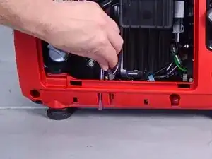
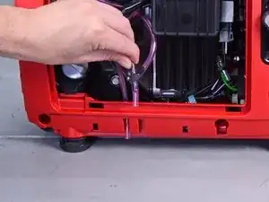
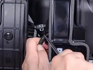
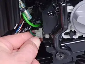
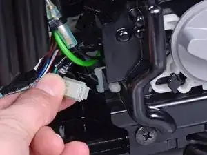
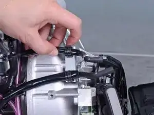
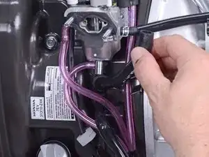
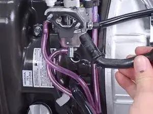
    • Use a screwdriver to pry and loosen the diaphragm tube from the fuel pump.

    • Disconnect the diaphragm tube from the fuel pump.

  23. rDfH4SuJGIPQw3nA
    rDfH4SuJGIPQw3nA
    IvZOVneeE4UYbm1Z
    • Use a pair of pliers to squeeze and slide the spring clip off the fuel pump port.

  24. rTyxwyfquPETICC2
    rTyxwyfquPETICC2
    vHCSGTDrBmW4kNYt
    • Residual fuel may leak out of this hose. Be ready to contain any spillage.

    • Disconnect the fuel hose from the fuel pump.

  25. mOuc2RhtyTgHJSkg
    mOuc2RhtyTgHJSkg
    fbd1BSb6PTlYyC3Z
    • Pull and disconnect the engine stop switch connector from its socket.

  26. DUrKU2vvQkXpTLPg
    • Remove the Phillips screw securing the starter rope guide.

  27. DXHdkjeQIACXbXbU
    DXHdkjeQIACXbXbU
    MEquTWeCPuBXi5J1
    • Feed the starter rope handle and guide through the panel cutout.

  28. yxffS2fuc5fnQSHx
    yxffS2fuc5fnQSHx
    xuaOgVSje5dODYlV
    • Any residual fuel in the tank will leak. Be ready to contain any spillage.

    • Use a pair of pliers to squeeze and slide the spring clip off the fuel tank port.

  29. PZLSvRbpsPUWuJWu
    PZLSvRbpsPUWuJWu
    Yl5OMBwZQREoXGpa
    • Disconnect the fuel line and filter from the fuel tank.

  30. di4bvofG3VfoiN3K
    • Remove the Phillips screw securing the left (non-access) frame assembly.

  31. oYTrCoG1XKHXLROE
    oYTrCoG1XKHXLROE
    SRMlEFYTSPB5KNWd
    • Remove the left (non-access) frame assembly.

  32. ThJcW4NGXxYtTOSa
    ThJcW4NGXxYtTOSa
    UBHdr2RHV3NgXghD
    • Lift and remove the fuel tank.

  33. ynfUXaH52i3lIy2G
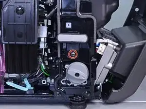
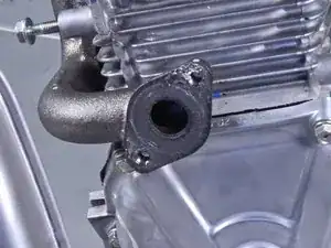
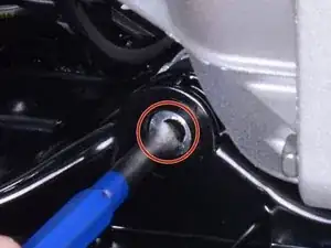
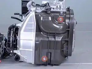
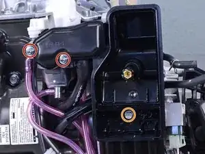
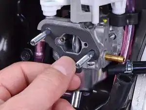
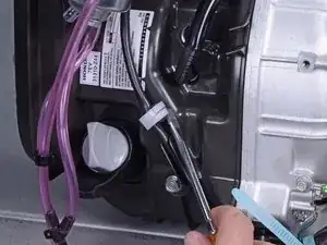
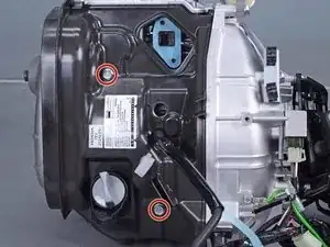
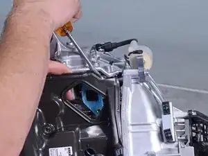
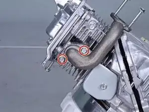
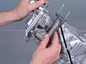
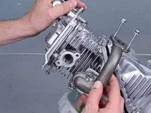
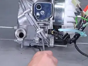
    • Use a 10 mm socket to remove the three bolts securing the muffler:

    • Two 50 mm-long bolts

    • One 75 mm-long bolt

    • During reassembly, these bolts should be tightened to 8.7 lb-ft.

  34. xUJDTWJnpASCJNJM
    • Remove the muffler.

  35. KGoIiLiH3IfrVIvT
    • Use a wire brush to clean any deposits off the spark arrester.

  36. DZdZCvq1ULDl3OIN
    • During reassembly, replace the muffler gasket if it shows signs of wear.

  37. Ob2OmdTgF2eOA6lw
    • Use a flathead screwdriver to pry up the blue wire harness from the under-cover.

  38. QdRGaMaxlxTKpFsU
    QdRGaMaxlxTKpFsU
    6wqE3xG4M1Amw1Vo
    uBEMUYvTngvPxGRT
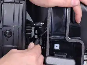
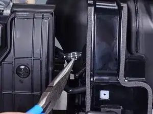
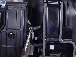
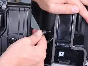
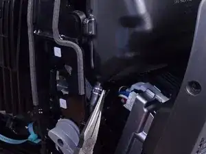
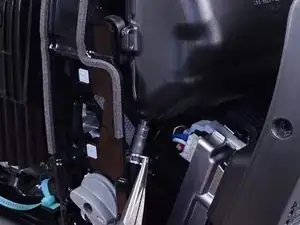
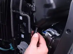
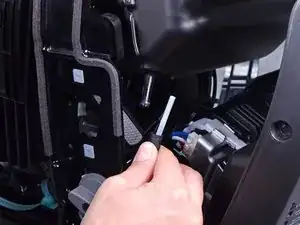
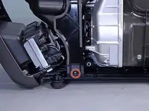
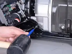
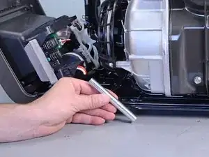
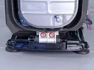
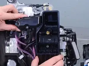
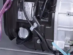
    • Use a mallet and punch to tap out the front collar (closest to the electrical panel) securing the motor assembly to the under-cover.

  39. WnfXGoLccUsoxVBZ
    • Use a 10 mm socket to remove the two bolts securing the motor rear to the under-cover.

  40. NfkFR2LWTIxps4lb
    NfkFR2LWTIxps4lb
    c3Jmr2Jbq5TNFDOF
    yXNcW2lVT3p5Y1WW
    • The motor assembly is heavy. Follow safe lifting practices when you lift the assembly.

    • Lift the motor assembly off the under-cover and set it aside.

  41. kOyoRVnISJZSacDx
    • Use a 10 mm socket to remove the two bolts securing the left shroud.

  42. 5CNMdUsaVW2mX2NI
    5CNMdUsaVW2mX2NI
    CLJPxks1uSDVm2vT
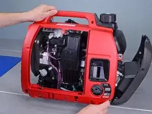
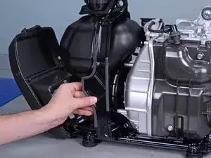
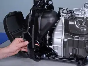
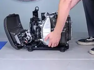
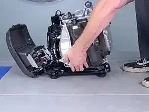
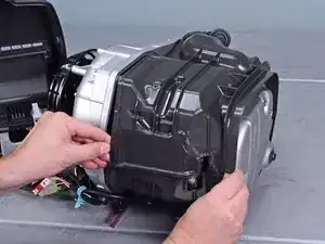
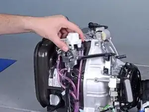
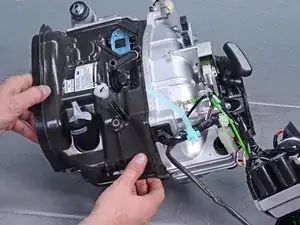
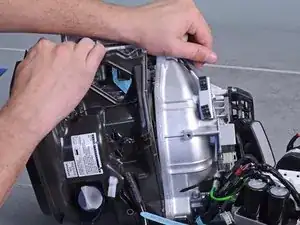
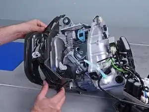
    • Begin separating the left shroud from the engine assembly by pulling it away from the assembly.

    • The shroud sits in a groove on the engine assembly and may take some force to pull out.

  43. nrAFxjdno2byyYu6
    nrAFxjdno2byyYu6
    KTipPsFHLTrLFAd6
    LWcXVCSdsUIBxlp1
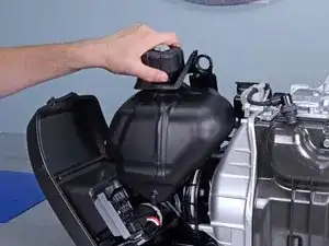
    • Pull along the edge of the shroud until you separate the shroud from the engine assembly.
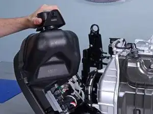
    • Remove the shroud.

  44. MRBUQXNuhS4DYljT
    MRBUQXNuhS4DYljT
    Xix2ONNCnoKrDPNK
    • Remove the Phillips screw securing the filter cover.

    • During reassembly, be sure to tighten the screw to at least 1.7 ft-lb to prevent it from loosening during operation.

    • Remove the filter cover.

  45. VMCCKESpTXlxJVSs
    VMCCKESpTXlxJVSs
    qh5DVFklMracAbxg
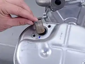
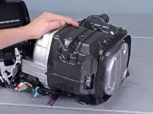
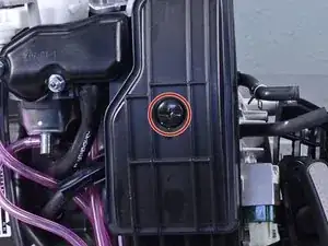
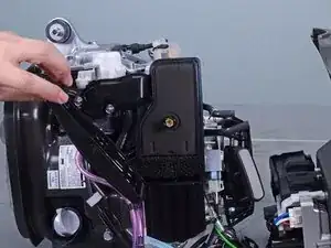
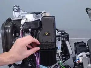
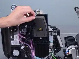
    • Remove the air filters from the filter box.

    • To clean the filters:

    • Clean the filters in warm soapy water

    • Allow the filters to dry thoroughly

    • Dip the filters in clean engine oil, and squeeze out excess oil

  46. MOB6YIGexpyaejgy
    MOB6YIGexpyaejgy
    YKQEPVJijLumYr1b
    • Disconnect the breather tube from the air cleaner housing.

  47. pxPfIAg1dm6aBT5r
    • Remove the following fasteners securing the housing:

    • Two 8 mm nuts

    • During reassembly, tighten these to 3.6 ft-lb.

    • One 8 mm bolt

  48. HXTR556GVcXHYsEn
    HXTR556GVcXHYsEn
    R2PEDSwvbvMCWPSw
    • Remove the air filter housing.

  49. NruJFjcBrNRoy1jS
    • During reassembly, replace the air intake gasket if it shows signs of wear.

  50. ImaungJbcKWnR4ay
    • During reassembly, use this photo as a reference for how to route the hoses.

  51. 1FkEIIltoZBPDWhc
    1FkEIIltoZBPDWhc
    UTQonQTlZ3ssxuyf
    KXmYusEirFT1l2hI
    • Unclip the fuel and air hoses from the side of the motor assembly.

  52. 5bEROEPJqwYRmyji
    5bEROEPJqwYRmyji
    nCA1xQvRsIYM4F5T
    • Pull the breather tube straight out of its port.

  53. 63DHWpukmEg6glJT
    63DHWpukmEg6glJT
    V2BRcT4fZFbMKdkQ
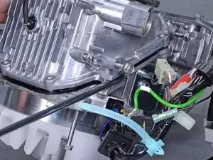
    • Use a flathead screwdriver to unclip the carburetor wires from the side of the motor assembly.

  54. rcmBFU4dTkM1QXCY
    rcmBFU4dTkM1QXCY
    NjLPEDvjZhy2b2DR
    • Slide the carburetor off its two bolt rails.

  55. ebQKOKSX4shnxWRD
    • During reassembly, replace the carburetor seal if it shows signs of wear.

  56. ZmJGS3FIDRjmIZXr
    • Use an 8 mm socket to remove the two bolts securing the carburetor insulator.

    • During reassembly, tighten these bolts to 2.2 ft-lb.

  57. wxSd122xvGf4oJWd
    wxSd122xvGf4oJWd
    ymfhpP6cnqjJciCZ
    • Remove the carburetor insulator along with the two bolt rails.

  58. YkPRgkLjHlVZdaPg
    • During reassembly, replace the insulator gasket if it shows signs of wear.

  59. WKQJNtnvbhKDNHT5
    • Use a 10 mm socket to remove the bolts securing the right shroud.

  60. QUAVFrPLgQudFPic
    QUAVFrPLgQudFPic
    dnGRyiePQvtytABA
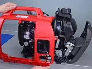
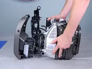
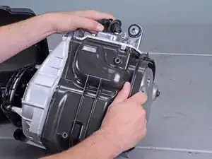
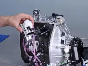
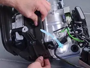
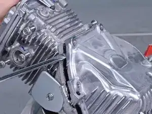
    • Begin separating the right shroud from the engine assembly by pulling it away from the assembly.

  61. hLCiNxJ6wMVhRyTc
    hLCiNxJ6wMVhRyTc
    KvOGej6YPZJgOM3d
    EKQtosF1G1GCGuvs
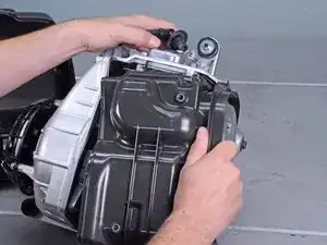
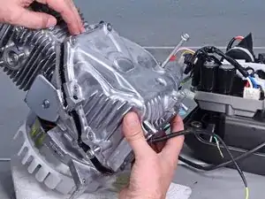
    • Pull the shroud away along the edge. Use a flathead screwdriver to pry it out of the engine assembly groove.

    Here you should remove the aluminum bell housing first, that way you don’t need to force the plastic part off the housing.

    cgonzalez19835 -

  62. IXmnnSKW52ucbJtP
    IXmnnSKW52ucbJtP
    kBVjQgWFA1SAL6d1
    • Remove the right shroud from the engine assembly.

  63. egNUE4UjxXBQYU2A
    • Use a 10 mm socket to remove the two bolts securing the exhaust pipe.

  64. U2SHbZMHlTl5GKHm
    U2SHbZMHlTl5GKHm
    iAkDe4X4NlUWIwL4
    • Remove the exhaust pipe from the engine assembly.

  65. SfmEr6Jr4egNvxR1
    • Loosen the cable tie securing the engine oil sensor.

  66. KMhgUYth6EWKggEA
    KMhgUYth6EWKggEA
    T1Nyc6Q1FOIY1gQg
    • Disconnect the yellow engine oil sensor wire by pulling the connector apart.

  67. CivpUxIt3YfVcXaB
    CivpUxIt3YfVcXaB
    M1PFJRPWTdUVRLIJ
    • Use a 10 mm socket to remove the bolt securing the engine oil sensor ground.

  68. DyByQQEyEavB4gjI
    DyByQQEyEavB4gjI
    u5cdD3RmoTBZ246j
    • Use a 10 mm socket to remove the eight bolts securing the crankcase cover.

    • During reassembly, hand-tighten the crankcase cover bolts in the pattern indicated in the second image.

  69. PwhwWuVQPX2eHfSv
    PwhwWuVQPX2eHfSv
    1xbItG6HaD6WW3Hf
    HaNK4tkAM2EGyUn5
    • The crankcase cover is sealed with liquid sealant and must be pried apart.

    • Be ready to contain any residual engine oil that may spill from the crankcase.

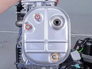
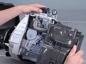
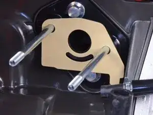
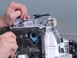
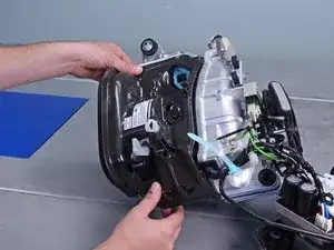
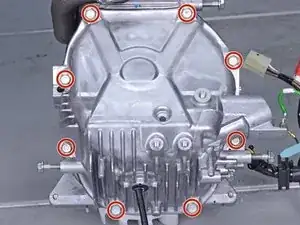
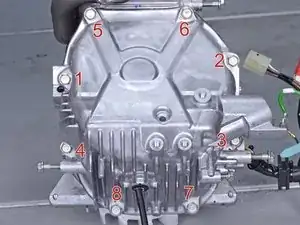
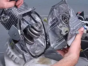
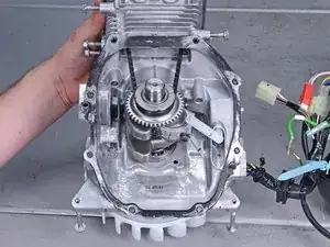
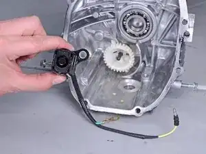
    • Insert a large flathead screwdriver or pry bar into the crankcase seam and pry to loosen the crankcase cover.

    • Do not use too much force, or you may gouge the mating surface.

    • Pry along the entire crankcase perimeter until you fully loosen the crankcase cover.

  70. XlJLGXvOHKVKEHRb
    XlJLGXvOHKVKEHRb
    rMqaxhCUYju446KL
    • Separate and remove the crankcase cover.

  71. dsh4N1sW4YTYafJm
    • To reseal the crankcase during reassembly:

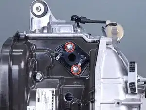
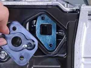
    • Clean all adhesive and oil residue off of the cover and crankcase mating surfaces.

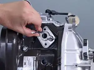
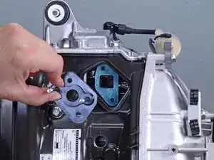
    • Apply a bead of liquid sealant to the crankcase.

    • Fit the crankcase cover to the crankcase.

    • Do not fill the crankcase with engine oil for at least 20 minutes after sealing the crankcase.

  72. e2EVJCAx3FnxFLdK
    • Use a 10 mm socket to remove the bolt securing the oil level sensor.

  73. VKDEaBH6mxgnZVeJ
    VKDEaBH6mxgnZVeJ
    NZ2jkkTEokDXJPDK
    OPJWMZvyIXteOqQa
    • Thread the sensor cable through the port and remove the sensor.

    • Be sure to check if your replacement sensor has an O-ring pre-installed on the sensor's mating surface. If it doesn't, transfer the O-ring over.

Conclusion

To reassemble your device, follow these instructions in reverse order.

Arthur Shi

Member since: 03/01/18

248651 Reputation

0 comments