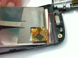
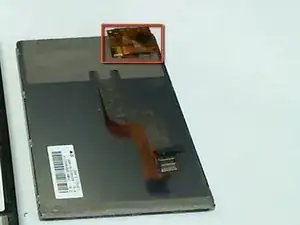
Introduction
Tools
Parts
-
-
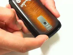
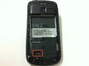
Press both thumbs on each side of the upper corners, and apply pressure in a downward motion.
-
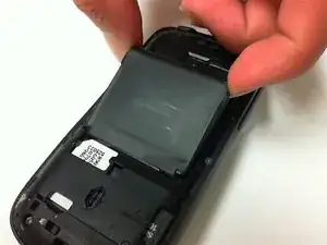
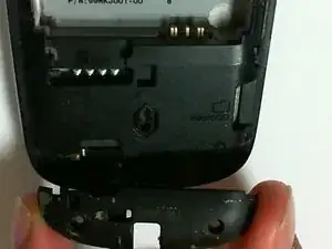
While applying downward pressure, slide the back cover down and off the phone.
-
-
-
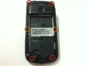
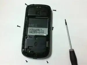
Remove the four 6 mm T5 Torx screws from the four corners on the back of the phone.
-
Remove the two 4 mm T5 Torx screws from the middle of the back of the phone.
-
-
-
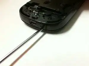
Insert a spudger into the gap between the frame and cover. Push downward with the spudger to separate the back plate from the phone.
-
With the spudger in the gap between the frame and cover, move the spudger around the edge of the of the phone to finish removing the back plate.
-
-
-
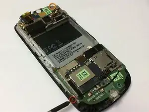
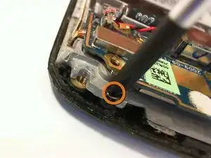
Remove the 3 mm Phillips screw located on the side of the bottom left-hand corner of the phone.
-
Remove the 3 mm Phillips screw located on the top right-hand corner of the phone.
-
-
-
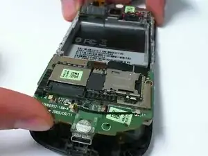
Place a finger between the circuit board and front cover, and lift the circuit board gently.
-
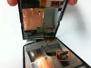
Separate the circuit board from the front cover and screen to access the ribbon cable holding them together. Detach the ribbon cable.
-
Finish separating the circuit board from the front panel.
-
-
-
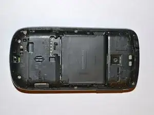
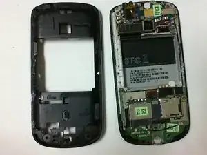
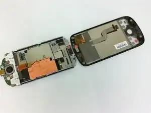
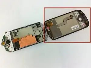
After following the prerequisite guide listed above, the phone should have the circuit board housing group on one piece.
-
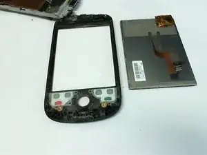
The front cover and screen of the phone should be located on the other piece.
-
-
-
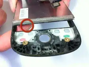
Place a finger on the front side of the screen, and push up as indicated.
-
Carefully grab onto the sides of the LCD and glass screen.
-
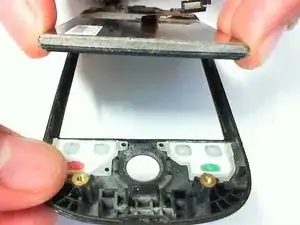
Continue to angle the LCD and glass screen further up.
-
-
-
Carefully lift the screen away from the front cover.
-
The adhesive should be easy to separate while separating the front cover from the screen.
-
To reassemble your device, follow these instructions in reverse order.
