Introduction

  1. NUEjZhsfWkcnKF3p
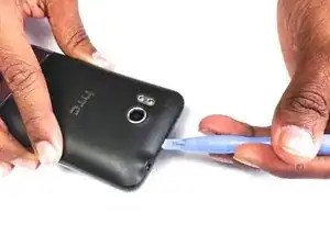
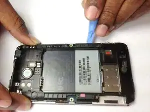
    • Insert the plastic opening tool into the top of the Thunderbolt near the power button.

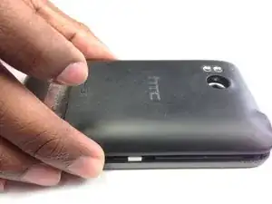
    • Gently pry up on the rear panel around the edges until it is loose.

  2. IWNHBrwDmZ6i4NlE
    • Lift and remove the rear panel.

  3. KNKhwHaKgyVpa3dp
    KNKhwHaKgyVpa3dp
    d5QDNcaYvPYSFCmU
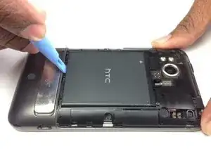
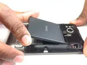
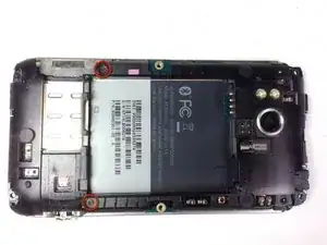
    • Using the plastic opening tool, lift up the battery from the bottom near the kickstand.

    • Remove the battery from the inner frame.

  4. IWlRH5CRoTAdQ5Lw
    IWlRH5CRoTAdQ5Lw
    a4BoFdlh6PQQXYWS
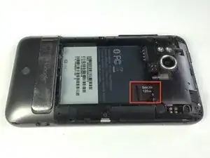
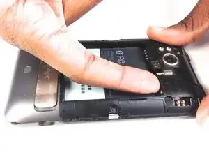
    • Use your finger to push the MicroSD card in towards the top of the phone, allowing it to be released from the casing.

  5. yqUkZADyJixWXSaO
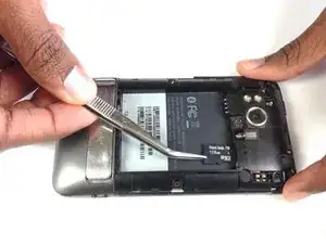
    • Use tweezers to grab onto the MicroSD card and carefully remove it from the casing.

  6. kTWPk5Jwie5EIvAA
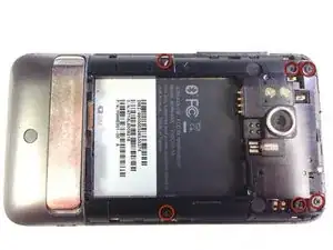
    • Remove the six Phillips screws from the perimeter of the rear frame.

    • By removing the screw with the "void" sticker on it, your Thunderbolt will no longer be covered under warranty.

  7. MqbX6rtKLZaWAG2m
    MqbX6rtKLZaWAG2m
    jvKso2EBAdIhr3QR
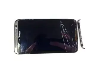
    • Insert the plastic opening tool into the bottom of the phone underneath the soft keys.

    • Gently pry up on the plastic cover by sliding the plastic opening tool across the bottom of the phone.

    • Remove the plastic cover.

    • The plastic cover will have adhesive on it making it difficult to remove.

  8. xG1In4LtSvQkDFCY
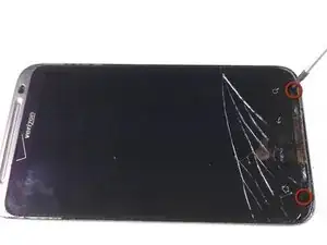
    • Remove the two Phillips screws where the plastic cover was.

  9. RHhuNnMxANtXs5ha
    RHhuNnMxANtXs5ha
    FWEBBqde6WMT5ZRe
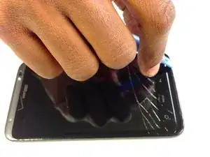
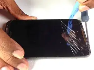
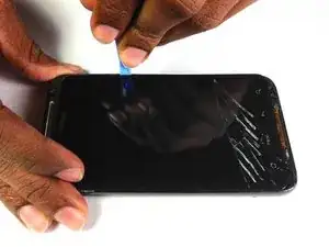
    • Insert the plastic opening tool in between the screen and the frame on the side of the phone.

    • Slowly slide the the plastic opening tool along the side of the phone until the screen begins to separate from the frame.

    • Do the same for the opposite side of the phone.

  10. lxdNNbWjUJRnKKhC
    lxdNNbWjUJRnKKhC
    NXPKYjWbIbiHFPaK
    UVeLQRrUTSWPm4U1
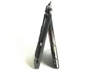
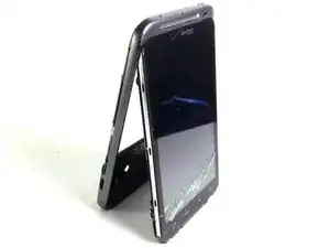
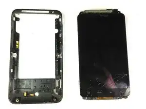
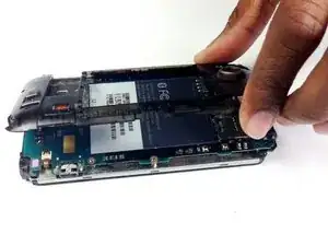
    • Carefully separate the screen and phone from the rear frame, starting from the bottom.

    • Gently pull down on the phone and screen to fully separate it from the rear frame.

  11. 6tFHNQtXNJGuwWCI
    • Remove the two Phillips screws securing rear inner frame to device.

  12. CndW4YcNY2QmfLgh
    • Insert the plastic opening tool between the rear inner frame and the motherboard and slowly work your way around the device.

  13. KjAPU2BbPugMCpZh
    KjAPU2BbPugMCpZh
    nJxGSx1qJNTUfwLO
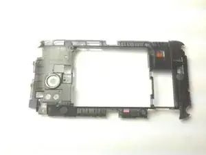
    • Remove the rear inner frame from the rest of the device.

  14. M4grmxIxyhSOsp55
    M4grmxIxyhSOsp55
    Tt5JSrXPfmoWq44m
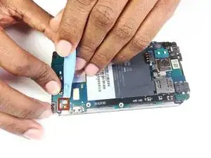
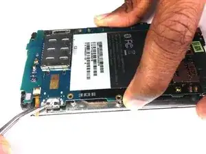
    • Using the tip of an plastic opening tool flip up the tab holding the capacitive button ribbon cable.

    • Be careful opening these tabs as they are very easy to break.

    • Use a pair of tweezers to pull the capacitive button cable out of its socket.

  15. iXYulYjj51564QYR
    iXYulYjj51564QYR
    CYdwVPDAnUcDvqS4
    • Lifting from the side where the ribbon was disconnected, flip over the motherboard.

    • Remove the black tape covering the tabs connecting the motherboard and LCD.

  16. DVDqxG5p1ODwywTN
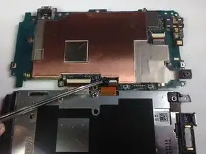
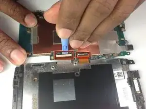
    • Using the plastic opening tool pop up the two tabs connecting the LCD and motherboard.

  17. F1xDuJlLlRXEZiWX
    F1xDuJlLlRXEZiWX
    khVqJmOKoLHkfOTk
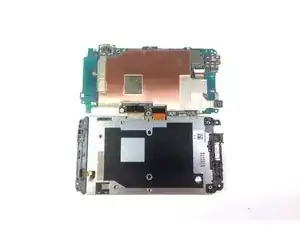
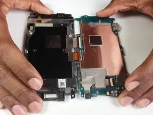
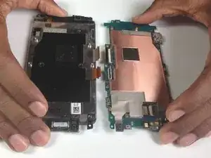
    • Once the tabs have been popped up, slowly pull the two pieces away from each other.

    • If there is resistance pulling apart the phone then a ribbon or tab has not been disconnected properly/completely.

Conclusion

To reassemble your device, follow these instructions in reverse order.
Brandon Younger

Member since: 17/01/13

212 Reputation

0 comments