Introduction

Users will be able to replace their damaged camera and regain functionality. The camera replacement requires the removal of both the motherboard and the camera chip to remove the camera. Be careful not to damage any other components during the repair.

  1. Q6Fwl1hL2JqcjLRH
    Q6Fwl1hL2JqcjLRH
    1AuKTnITcBMDxwP2
    RhjU3tcTKxyP4e1M
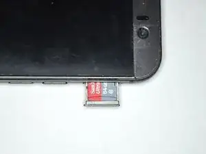
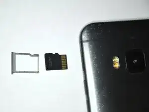
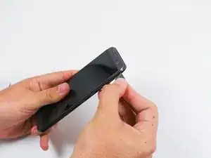
    • The microSD card tray is located on the upper right hand side of the phone, above the volume buttons. To open the tray, insert a microSD card eject tool, or a paperclip, into the small hole in the microSD card tray.

    • Then press the tool or paperclip to eject the microSD card tray.

    • This may require a significant amount of force.

    • When reinserting the microSD card, ensure that it is in the correct orientation to the tray. The electrical connectors should be inserted first, with the microSD card face up.

    • It is normal for the microSD to sit imperfectly in the tray. The microSD card is easy to reposition within the tray.

  2. ahkPIQBTYMIg1N4Y
    ahkPIQBTYMIg1N4Y
    DELV2eZ4SFJ4rENE
    1O2YnSdIWhrujfuH
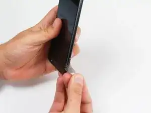
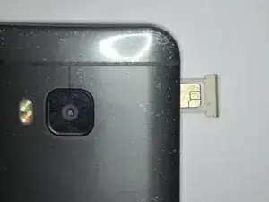
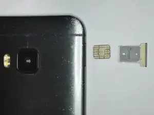
    • Insert a SIM card eject tool or a paperclip into the small hole besides the SIM card tray, located on the upper section of the left edge of the phone.

    • Press to eject the tray.

    • This may require a significant amount of force.

    • When reinserting the SIM card, ensure that its contacts are facing to the rear side. The tapered corner of the SIM card has to point to the outer bottom corner of the tray.

  3. UDwLUrKwYQxjjaTD
    UDwLUrKwYQxjjaTD
    UnVGLBanACA4GZaD
    uD2foUpDIjmKIcWt
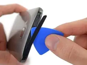
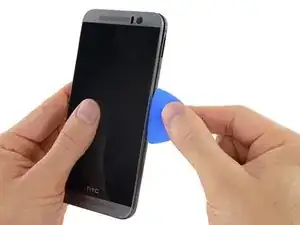
    • Using a plastic opening pick or a spudger, gently pry and remove the cover on top of the case.

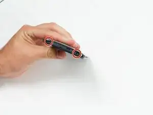
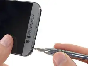
    • Remove the two 4 mm T5 Torx screws on the top of the case.

    Be sure to remove the SIM tray and memory card tray prior to removing back case! Bent mine because that step was missing.

    cameronb -

    The black plastic piece that runs across the top is very thin and is stuck on with very strong tape.

    SMcC21985 -

  4. vJMd1cvotNQHBjn4
    vJMd1cvotNQHBjn4
    jWUMJ2OiPHr1aesu
    JCHJGYX6viJQGcVf
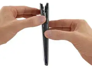
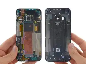
    • Work a plastic opening pick around the perimeter of the device to separate the rear case from the display assembly.

    • The SIM card tray and Micro SD card tray must be removed before the back cover can be removed.

    • Be careful around the power and volume buttons, as they are fairly delicate.

    • Be careful when separating the body from the display assembly, as the rear-facing camera may be stuck to the body with adhesive.

    The SIM Card and SD Card's need to be removed before the case will come apart.

    Andrew Froude -

    I found a video showing someone using a 2 to 3 inch length scraper razor blade around the perimeter. On my second HTCM9 battery swap I found that leading with a square tipped X-Acto blade to begin the opening, and leaving the trailing, “already opened” gap “wedged” open with the scraper blade helped smoothly open from top (IR header) to bottom (micro USB charger port). A conventional spudger pries open too quickly and can damage and misshape the LCD’s soft bezel. The bezel surround is a much softer compound than the rear case. You can work the rear case loose by gently prying the back’s perimeter outward and occasionally inward as you progress. There are four tabs on the LCD assembly (i.e. nearby and under the pliers in step 5) on each side that protrude into the rear case. Push in toward the back, and pry outward on the back case seam around the vicinity of the tabs. This action provides clearance for the tab to loose from the case tab slot.

    Michael K -

  5. 1iTcIShuKBayUStZ
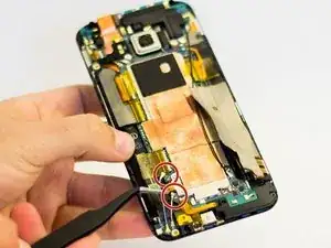
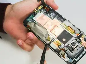
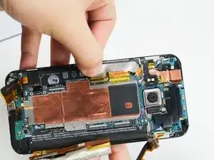
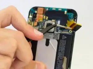
    • Use a pair of tweezers to get underneath the white and blue cable connectors and gently push them upwards to disconnect them.

    Blue coax cable.. what does it do?

    Yusuf Koçaslan -

  6. BILIFTEdHZvAfimH
    BILIFTEdHZvAfimH
    Q4wuGFuMoiZARIi5
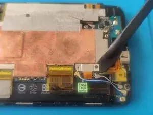
    • Remove the two 1.5 mm screws that secure the battery connector to the motherboard, using a Phillips #00 screwdriver.

    • Use a spudger to gently pry up the battery connector from its socket.

    • Do not apply pressure to the socket.

    When reassembling the phone, be sure to attach the battery connector correctly before screwing it down. It has a rectangular connector that may not seat correctly if simply screwed down.

    Jay Clark -

    On my new battery the connector was not aligned precisely so the battery was not connected properly to the motherboard after screwing it in. The connector is supposed to hold on it’s own without the screws. If the connector does not hold to the motherboard without the screws, make sure that the connector is actually plugged in properly and only screw it in once it holds by itself.

    Gerrit Addiks -

  7. PCNUjYfMVTwYPTbk
    PCNUjYfMVTwYPTbk
    eLBt1YI3PCoKXES3
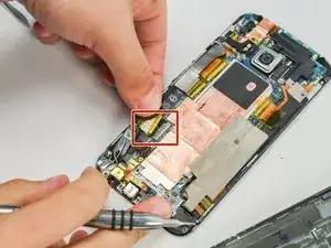
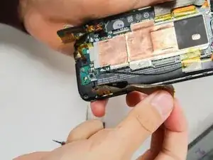
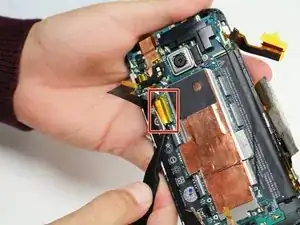
    • Peel back the Kapton tape from the ZIF connectors.

    • Use a spudger or your fingernail to lift the hinged retainer clips on the ZIF connectors, and gently slide the cables out.

    Lift up on the white portion of the connector

    Jarred Goar -

  8. ASoQkKUbqxxBMbjg
    ASoQkKUbqxxBMbjg
    qGvNlECIWgrvAQul
    r2yfnru4HRIiPLBK
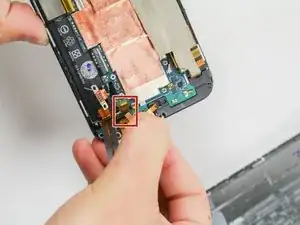
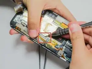
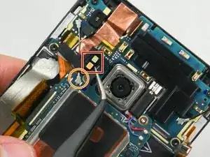
    • Using the tweezers, carefully lift the tape covering the electrical strip, as shown in the picture.

    • Be gentle when lifting the tape as it can tear easily.

    • Use a spudger or your fingernail to lift the hinged retainer clip on the ZIF connector, and slide the cable out.

    Mine did not have the piece of tape.

    SMcC21985 -

  9. 6SCxm5DV1oLOov5C
    6SCxm5DV1oLOov5C
    GETBJ2RCijVLioJZ
    bVWPFtIxpG3asAHG
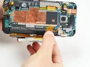
    • Peel back the Kapton tape from the remaining three ZIF connectors, then use a spudger or your fingernail to lift the hinged retainer clips on the ZIF connectors, and slide the cables out from each.

    • The third ZIF connector is mostly underneath the motherboard. When reassembling your device, make sure it is placed back underneath.

    For the featured ZIF header in step 10, which originates from under the circuit board, after liberating the yellow-clear tape I used a “Plackers” dental flosser “pointed end” to carefully lift up from under the ZIF ribbon.

    Michael K -

    the third connector what is that one for? my screen was sometimes flicker and that connector is loose from underneath the motherboard

    Sugar Bomb Gaming -

  10. ldmiwHDY6L6kfWgB
    ldmiwHDY6L6kfWgB
    WnLZw2aWfikATLF4
    LWju5YceEoWK4CHL
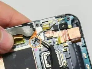
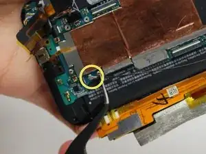
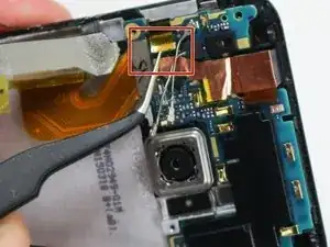
    • Remove the dual LED flash cover with a pair of tweezers. The cover is held on with a small amount of adhesive.

    • Using a heated pair of tweezers would ease the removal of flash cover, as the heat helps weaken the adhesive .

    • Remove the cover using a minimum amount of force. The flash cover may be glued to the antenna cable(s) below.

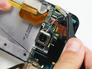
    • Use a pair of tweezers to disconnect the two antenna cables near the camera.

    • Some models of this phone will have only one antenna cable at this location.

    • Disconnect the antenna cable near the bottom right of the phone.

  11. qTLNA2BECGoefPUS
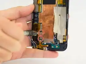
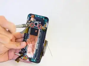
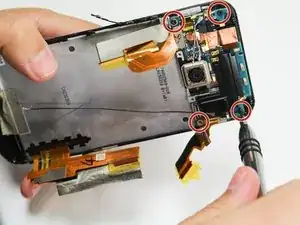
    • Remove the three 4 mm T5 Torx screws that secure the motherboard.

    Great guide just one crucial warning missing! When removing the battery which is underneath the power/SD/volume cable make sure you see that and carefully remove the battery without tearing it apart! Had to learn the hard way. Fortunately it's replaceable..

    Charles Vheru -

  12. 3SeUtvhXIDGWEdZB
    3SeUtvhXIDGWEdZB
    M1uYyPqN1skRnkPE
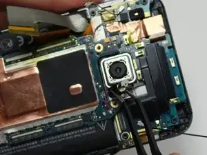
    • Use a pair of tweezers to lift the vibrator out of its slot.

    • Avoid damaging the wires connecting the vibrator to the motherboard. Use the minimum amount of force.

    • Use an iOpener or heat gun to loosen the adhesive at the bottom of the motherboard.

    • Refer to the iOpener Instructions for further info.

    • Use a plastic opening tool, or a spudger, along the edges of the case to gently pry the motherboard out of the case.

    • Gently lift the motherboard out of the case, beginning from the top corner (near the camera).

    Mine did not have any adhesive.

    SMcC21985 -

  13. 6LD2QFqpYY3hO4Zo
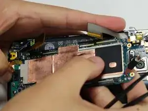
    • Remove the four 3 mm T5 Torx screws that secure the daughterboard.

  14. MaQXwAZxmXPUVvSR
    • Using the tweezers, disconnect the ribbon cable.

  15. 5WfhyfpgQUSsrO6l
    5WfhyfpgQUSsrO6l
    q6ehGgRAEnSalFvT
    • Using the tweezers, disconnect the ribbon cable from the daughterboard.

  16. bPjRPPgbSJBYP45r
    • Using the tweezers, remove the daughterboard from the device.

  17. VNr35LKtgsqRZRSA
    VNr35LKtgsqRZRSA
    g1U4lFCKxHRo4RM1
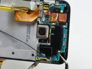
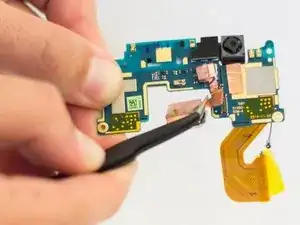
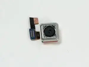
    • Flip the daughterboard over and use the tweezers to remove the back camera from the board by applying upward force to the ribbon connection.

Conclusion

To reassemble your device, follow these instructions in reverse order.

Michael Chan

Member since: 14/04/15

2336 Reputation

3 comments

In an attempt to replace the rear camera, the small black insert spaces for one of the SEVERAL ribbon cables breaks, the top portion where pins are located. I didn't discover this until after putting in the new camera. I was extremely careful when handling the cable and connector but I believe the connecting socket was already damaged and removing the ribbon and yellow tape delivered the killing blow. This resulted in the the phone not powering back on and increasing the repair cost of the phone too high (plus the connector was located on the main motherboard and I don't know how that repair would be done or if that would just reset the entire phone) I would honestly give this phone a 0/10 repairability. This was my first attempt at repairing a phone and I feel very defeated, that the phone just wasn't meant to be repaired with such weak connectors and rear camera glass in the first place. As for the guide, it was pretty good, more pictures and a possible video would be great.

Alexander Louria -

Nice! I just succesfully completed the rapair of the back camera.

Thanks!!

Pascallow -

Just fixed my camera. Don't know why its rated as hard. As long as you are careful and follow the instructions with the recommended tools anyone with basic tool familiarity can succeed. It did take almost 1.5 hours and I would recommend a lighted position able magnifying glass to assist in seeing the small parts. Awesome instructions. thank you for giving me a working camera again.
Garnet Burton -