Introduction

Use this guide to replace your HTC One M9's front speaker. This guide is essential if you want sound from your speakers back!

  1. Q6Fwl1hL2JqcjLRH
    Q6Fwl1hL2JqcjLRH
    1AuKTnITcBMDxwP2
    RhjU3tcTKxyP4e1M
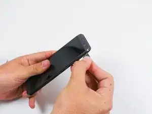
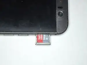
    • The microSD card tray is located on the upper right hand side of the phone, above the volume buttons. To open the tray, insert a microSD card eject tool, or a paperclip, into the small hole in the microSD card tray.

    • Then press the tool or paperclip to eject the microSD card tray.

    • This may require a significant amount of force.

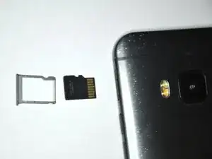
    • When reinserting the microSD card, ensure that it is in the correct orientation to the tray. The electrical connectors should be inserted first, with the microSD card face up.

    • It is normal for the microSD to sit imperfectly in the tray. The microSD card is easy to reposition within the tray.

  2. ahkPIQBTYMIg1N4Y
    ahkPIQBTYMIg1N4Y
    DELV2eZ4SFJ4rENE
    1O2YnSdIWhrujfuH
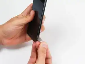
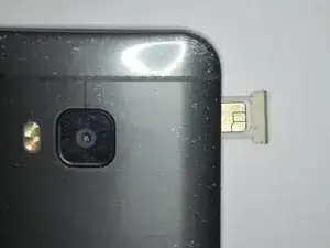
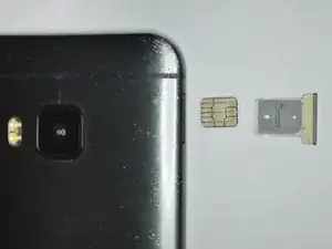
    • Insert a SIM card eject tool or a paperclip into the small hole besides the SIM card tray, located on the upper section of the left edge of the phone.

    • Press to eject the tray.

    • This may require a significant amount of force.

    • When reinserting the SIM card, ensure that its contacts are facing to the rear side. The tapered corner of the SIM card has to point to the outer bottom corner of the tray.

  3. UDwLUrKwYQxjjaTD
    UDwLUrKwYQxjjaTD
    UnVGLBanACA4GZaD
    uD2foUpDIjmKIcWt
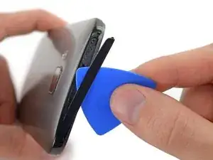
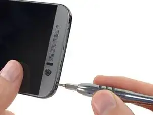
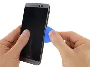
    • Using a plastic opening pick or a spudger, gently pry and remove the cover on top of the case.

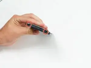
    • Remove the two 4 mm T5 Torx screws on the top of the case.

  4. vJMd1cvotNQHBjn4
    vJMd1cvotNQHBjn4
    jWUMJ2OiPHr1aesu
    JCHJGYX6viJQGcVf
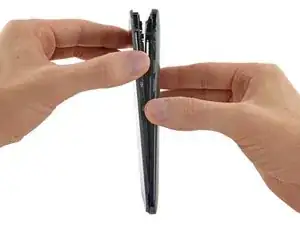
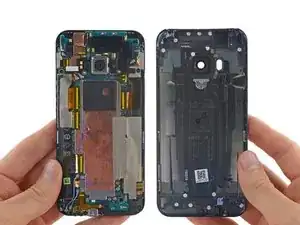
    • Work a plastic opening pick around the perimeter of the device to separate the rear case from the display assembly.

    • The SIM card tray and Micro SD card tray must be removed before the back cover can be removed.

    • Be careful around the power and volume buttons, as they are fairly delicate.

    • Be careful when separating the body from the display assembly, as the rear-facing camera may be stuck to the body with adhesive.

  5. 1iTcIShuKBayUStZ
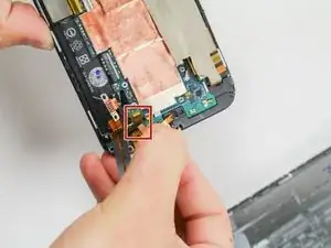
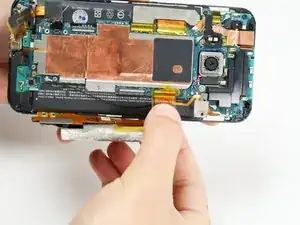
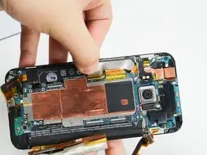
    • Use a pair of tweezers to get underneath the white and blue cable connectors and gently push them upwards to disconnect them.

  6. BILIFTEdHZvAfimH
    BILIFTEdHZvAfimH
    Q4wuGFuMoiZARIi5
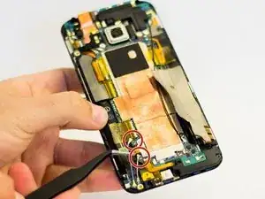
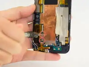
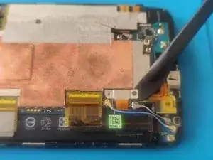
    • Remove the two 1.5 mm screws that secure the battery connector to the motherboard, using a Phillips #00 screwdriver.

    • Use a spudger to gently pry up the battery connector from its socket.

    • Do not apply pressure to the socket.

  7. PCNUjYfMVTwYPTbk
    PCNUjYfMVTwYPTbk
    eLBt1YI3PCoKXES3
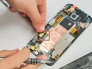
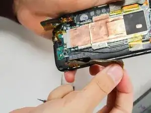
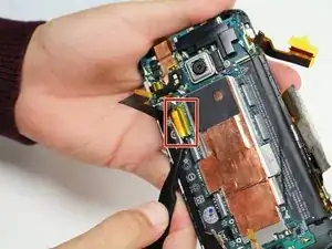
    • Peel back the Kapton tape from the ZIF connectors.

    • Use a spudger or your fingernail to lift the hinged retainer clips on the ZIF connectors, and gently slide the cables out.

  8. ASoQkKUbqxxBMbjg
    ASoQkKUbqxxBMbjg
    qGvNlECIWgrvAQul
    r2yfnru4HRIiPLBK
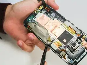
    • Using the tweezers, carefully lift the tape covering the electrical strip, as shown in the picture.

    • Be gentle when lifting the tape as it can tear easily.

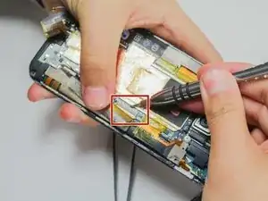
    • Use a spudger or your fingernail to lift the hinged retainer clip on the ZIF connector, and slide the cable out.

  9. 6SCxm5DV1oLOov5C
    6SCxm5DV1oLOov5C
    GETBJ2RCijVLioJZ
    bVWPFtIxpG3asAHG
    • Peel back the Kapton tape from the remaining three ZIF connectors, then use a spudger or your fingernail to lift the hinged retainer clips on the ZIF connectors, and slide the cables out from each.

    • The third ZIF connector is mostly underneath the motherboard. When reassembling your device, make sure it is placed back underneath.

  10. ldmiwHDY6L6kfWgB
    ldmiwHDY6L6kfWgB
    WnLZw2aWfikATLF4
    LWju5YceEoWK4CHL
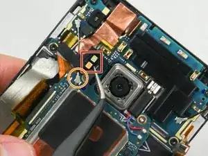
    • Remove the dual LED flash cover with a pair of tweezers. The cover is held on with a small amount of adhesive.

    • Using a heated pair of tweezers would ease the removal of flash cover, as the heat helps weaken the adhesive .

    • Remove the cover using a minimum amount of force. The flash cover may be glued to the antenna cable(s) below.

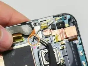
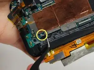
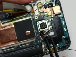
    • Use a pair of tweezers to disconnect the two antenna cables near the camera.

    • Some models of this phone will have only one antenna cable at this location.

    • Disconnect the antenna cable near the bottom right of the phone.

  11. qTLNA2BECGoefPUS
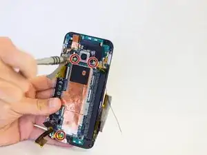
    • Remove the three 4 mm T5 Torx screws that secure the motherboard.

  12. 3SeUtvhXIDGWEdZB
    3SeUtvhXIDGWEdZB
    M1uYyPqN1skRnkPE
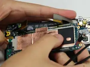
    • Use a pair of tweezers to lift the vibrator out of its slot.

    • Avoid damaging the wires connecting the vibrator to the motherboard. Use the minimum amount of force.

    • Use an iOpener or heat gun to loosen the adhesive at the bottom of the motherboard.

    • Refer to the iOpener Instructions for further info.

    • Use a plastic opening tool, or a spudger, along the edges of the case to gently pry the motherboard out of the case.

    • Gently lift the motherboard out of the case, beginning from the top corner (near the camera).

  13. 1yv16ioEIqh15lCE
    1yv16ioEIqh15lCE
    U2DRt4r5j5JEMSbM
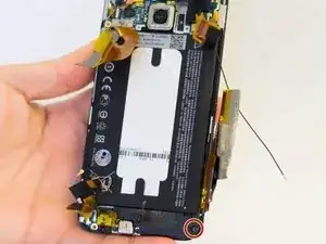
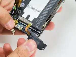
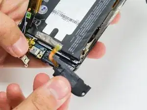
    • Remove the 3 mm T5 screw that holds the front speaker in place.

    • This screw was missing due to mishandling in an earlier deconstruction.

    • Gently remove the speaker from the device.

Conclusion

To reassemble your device, follow these instructions in reverse order.
Jonathan Chianglin

Member since: 14/04/15

487 Reputation

0 comments