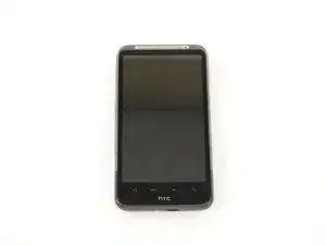
Introduction

This is not a pleasant repair. The device is full of adhesive. Removing the display assembly from front panel (or "mid chassis") can easily result in the destruction of the front panel bezel and digitizer. I suggest that you replace the entire digitizer, rather than one portion. If you want a beautiful front panel bezel, you will definitely need to replace that part, as well.

  1. iRUfdNxFOkQ5kj11
    iRUfdNxFOkQ5kj11
    KRjatFuSX1ygMhTj
    wJpwAAKVeryrewxZ
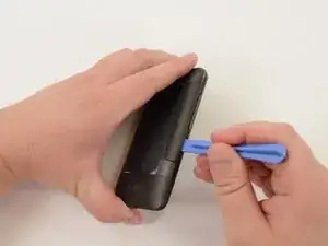
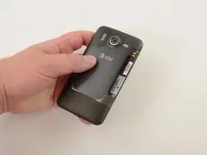
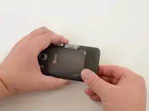
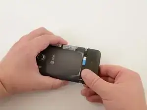
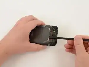
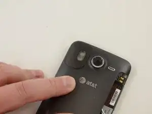
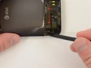
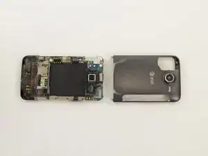
    • Remove battery cover using a plastic opening tool or finger nail.

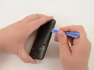
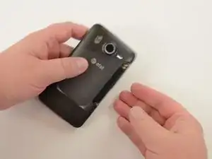
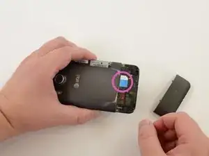
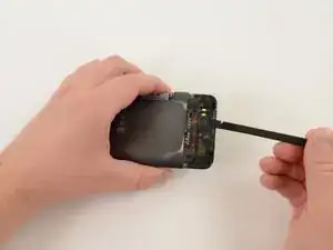
    • Slide opening tool to release clasps and remove battery cover.

  2. leN52eNIXpITWUmZ
    leN52eNIXpITWUmZ
    iNRTBlRRUGHQveQW
    2vw3GsRVt2EggD4e
    • With the cover removed, the battery will fall freely with a gentle shake.

  3. 1u24JmRBPgU3pOMm
    1u24JmRBPgU3pOMm
    RgL3CvHcKqwXNLnA
    • Remove SIM card cover by simultaneously squeezing cover and pulling it off of the phone.

  4. BsQHeSHX4CtiEPPP
    BsQHeSHX4CtiEPPP
    IcJdD6rk6AdQUbSy
    • Slide SIM card out.

  5. OiGQZXLa1jaU4Zt4
    OiGQZXLa1jaU4Zt4
    PUFk6IPXQES1OOJy
    FVOZArK6QQdw56Br
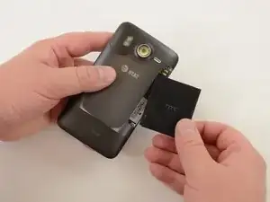
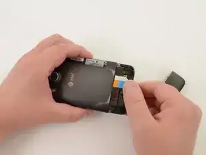
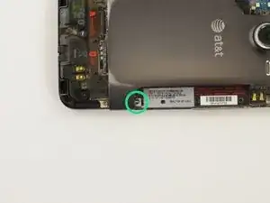
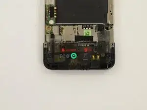
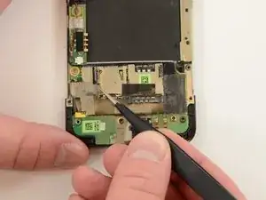
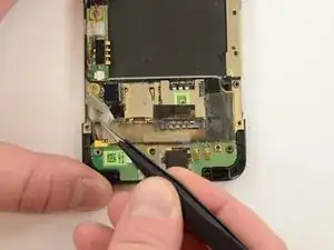
    • Remove Micro SD card by pushing it in to the phone. Spring-loaded clasp will release the card.

  6. mUUGjkOKoqqGH1Sp
    mUUGjkOKoqqGH1Sp
    MeI2216BcVhLLunM
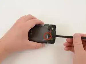
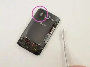
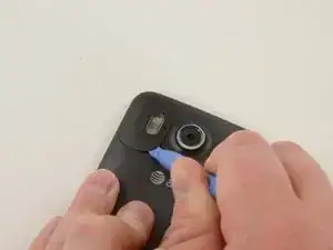
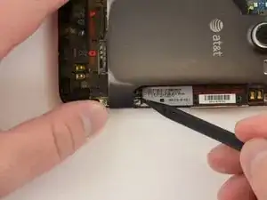
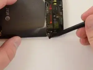
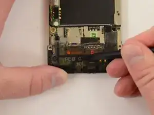
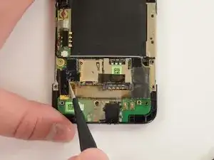
    • Use a curved metal spudger to remove GPS cover.

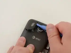
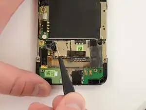
    • Probe underside of GPS cover until you can force a small opening between GPS cover and back cover of phone.

  7. ZDGJO2pOwZlpXS6k
    ZDGJO2pOwZlpXS6k
    DRrWFNxULTcIKQiJ
    XCwSDqmPq2X4v1g5
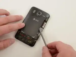
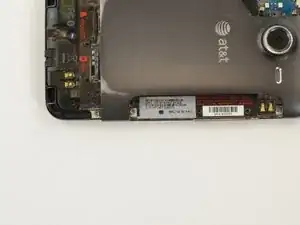
    • Insert plastic opening tool into gap between GPS cover and back cover of phone. Slide tool along GPS cover and pry the piece off.
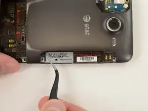
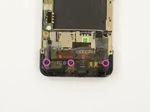
  8. vXLlgRQXZgLsnemC
    vXLlgRQXZgLsnemC
    r4VhHcpWEfXitoIQ
    yM44Poar6mxNJyXI
    • Remove "VOID" sticker from screw.

    • If your phone has a warranty, removing "VOID" sticker will void your warranty.

  9. fE2TVjB2kdfCs6j3
    fE2TVjB2kdfCs6j3
    Z5CGMlkBbbLmyxOD
    • Remove four 2.2mm T5 torx screws.

    • Remove one 4.5mm T5 torx screw.

  10. EDdEx5NBDYTOdFif
    EDdEx5NBDYTOdFif
    uVlBGJjLsbumaqtb
    • Remove display cable shield.

    • Insert probing tool into screw hole and pull shield.

    • Be careful! This piece is made of thin, springy metal and will fly across the room if you remove it too forcefully.

  11. 6QQij4S6yYDddLaS
    6QQij4S6yYDddLaS
    MLsdXEavKeIw3kse
    • Peel off manufacturer's information sticker.

  12. mQaSFF3FUINyl5TV
    mQaSFF3FUINyl5TV
    ijaOahM5q26KYE55
    • Lift volume button assembly out of the back case.

    • Work slowly! Initially, you must lever the assembly from the ribbon cable attaching it to the upper logic board. The cable is delicate.

  13. E1fVATYCBlGhNV2F
    E1fVATYCBlGhNV2F
    hwwrfqtdFav32LIE
    CNuorUDSSrJl3VUe
    • Push up on the back cover, wiggling cover back and forth, until it slides off.

  14. IZpkT6bsrBGc2vvh
    IZpkT6bsrBGc2vvh
    ZSITLk3WVY6k2Y2p
    c65nDeuFoJFdHKfQ
    • Remove "VOID" sticker.

    • If your phone has a warranty, removing the "VOID" sticker will void your warranty.

    • Remove three 2.4mm T5 torx screws.

  15. cDKC52udIXhoKgiZ
    cDKC52udIXhoKgiZ
    w4jaA6y2dNok1clw
    • Apply pressure to the bottom of the plastic logic board shield and it will pop right off.

  16. RpmZRjEUplxjaqbS
    RpmZRjEUplxjaqbS
    vBVhEB4qlwbinv1E
    • Remove rubber spacer.

  17. vsWfKUFMLTAkGpTk
    vsWfKUFMLTAkGpTk
    rFZTWJGh1lJCODKk
    • Peel off Mylar tape.

  18. 5kZFHXuaasIcZjPK
    5kZFHXuaasIcZjPK
    utxDecZapMtRKgSl
    • Peel off electrical tape.

  19. RKWmXAsFiHcCG1IA
    RKWmXAsFiHcCG1IA
    Ad1325PaTN3VJuFk
    F3FKmXdDVSKbGyGh
    • Pry display assembly connector off of lower logic board.

  20. alPRLjZFoMfwGmDt
    alPRLjZFoMfwGmDt
    QYPZDKNkWAgMwMbR
    • Remove metal bracket.

  21. ubGeHbRoxSPttPh5
    ubGeHbRoxSPttPh5
    ZjMsXAjwcBE1hQWc
    YGcnyplOD4G4dME5
    • Remove speaker.

    • During reassembly, be careful with the spring connectors on the reverse side of the speaker unit. They are bent easily.

    • This rubber spacer is held on by a weak adhesive. Be careful with this during reassembly, as it may catch and crumple as you put the back panel back the phone.

  22. SpPAKmbMb14Kgns1
    • Remove one 1.5mm #00 Phillips screw.

    • Remove two 2.5mm T5 torx screws.

  23. SlJo5RvWwWqC2AuC
    SlJo5RvWwWqC2AuC
    sBETJDfQUy6YpP2v
    • Remove earpiece speaker connector.

  24. WAWYdcKWYtCxsRYa
    WAWYdcKWYtCxsRYa
    DHIU5MMgUZXyTxED
    UycIPPFMbtHbTj2c
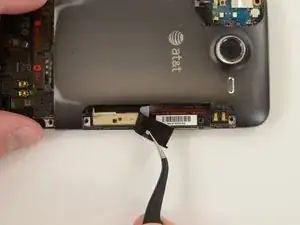
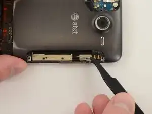
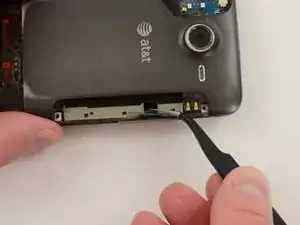
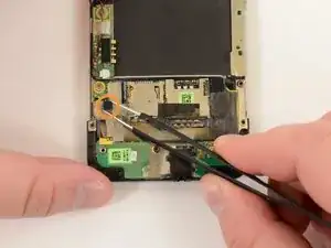
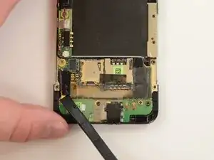
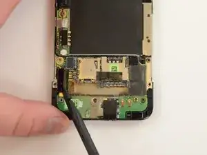
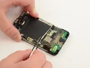
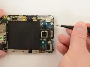
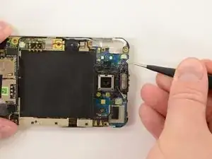
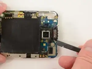
    • Pry off Bluetooth coaxial cable connector.

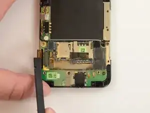
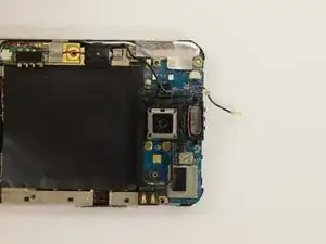
    • Unwind Bluetooth coaxial cable from plastic camera shield.

  25. GGnYvgueRg2KYog2
    GGnYvgueRg2KYog2
    TpjILN2bsF4tQ3lo
    62paRduxuo4csIon
    • Pry off plastic camera shield.

  26. 63nlav2EvmQPN4MO
    63nlav2EvmQPN4MO
    4VMToWj3pYhXNXtY
    • Heat black Mylar shield for easier removal.

    • As you can see, we attempted to peel off the Mylar shield before heating it. It required more force than we were comfortable with, so we turned up the heat!

    • Peel off Mylar shield.

  27. yKNp2vsmEKl2rbZn
    yKNp2vsmEKl2rbZn
    RQbOXJfAemQJKSDq
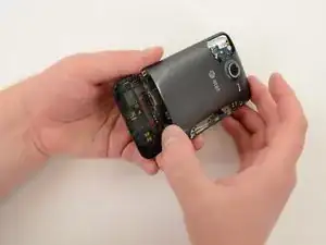
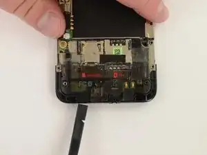
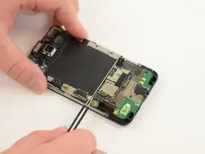
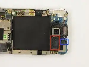
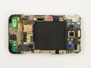
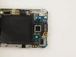
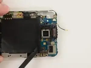
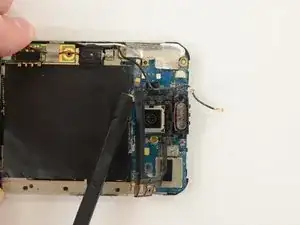
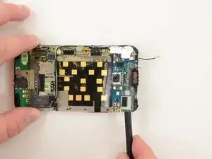
    • Gently separate upper logic board from mid chassis. The upper logic board is held to the mid chassis by copious amounts of strong adhesive.

  28. JkWHLSPEJApPDiV5
    JkWHLSPEJApPDiV5
    ckItUuclOUYETDJv
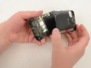
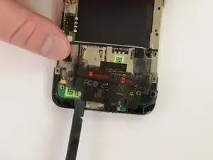
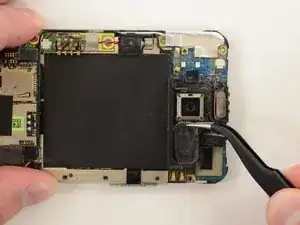
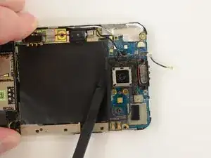
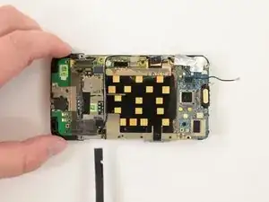
    • Gently separate lower logic board from mid chassis. The lower logic board is held to the mid chassis by copious amounts of strong adhesive.

  29. 6ISoBldXqVsqaHNo
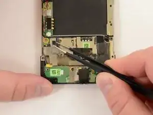
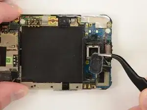
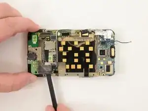
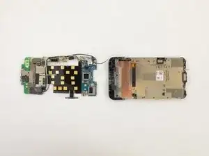
    • Once the adhesive-laden logic boards are separated from the mid chassis, the entire assembly easily comes off.

    • Be careful when handing the logic board assembly. We could have separated out each part, but decided it was a waste of time. The cost of cutting this corner is extra care when handling the logic board assembly.

    How to fix microphone

    cesarmg255 -

  30. aBhaEqZMFUFwk4mn
    aBhaEqZMFUFwk4mn
    JumhUjCdQdhBjHbM
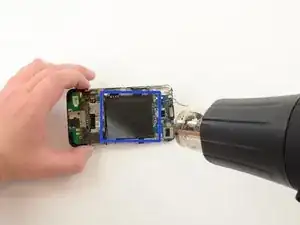
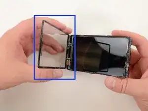
    • Blast the front panel with heat and pry between the display assembly and front panel bezel, working one or several guitar picks around the display assembly.

    • Once the display assembly is loosened from the front panel, it will fall away.

    • The front glass came off easily, but the digitizer was much more difficult to remove. The adhesive holding together the display assembly is much weaker than the adhesive holding the display assembly to the front panel.

    • While creating this guide, I utterly destroyed the front panel bezel and digitizer. Replacing the display assembly was a breeze--but removing the digitizer required nearly a dozen reheats of the front panel. To replace the bezel, you will need a new "mid chassis" (that's the front panel piece the digitizer is so powerfully glued to).

Conclusion

To reassemble your device, follow these instructions in reverse order.

Jeff Snyder

Member since: 07/02/13

8787 Reputation

0 comments