Introduction

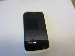
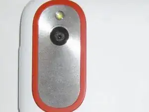
This guide will show you how to remove and replace the camera module of the HTC Desire V smartphone.

  1. 51UrWKe4ktasnGHl
    51UrWKe4ktasnGHl
    NcHfrTgsUoRva6yI
    CA2DpcYNmDrYDjIl
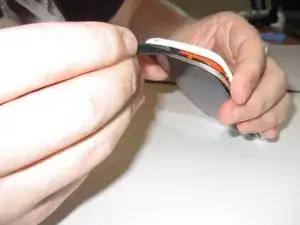
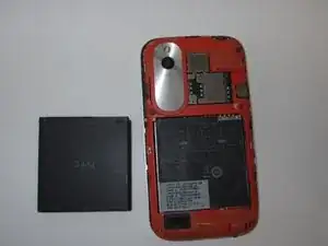
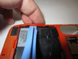
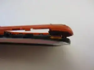
    • Gently pry back cover away from phone.

    • If you are having difficulty you may need to use a Spudger or plastic opener.

  2. mAdXU5TFQInQ1ixx
    mAdXU5TFQInQ1ixx
    LQ4hhGBKKL5KAA1q
    v6UpMKFlvyCaixIU
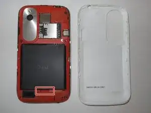
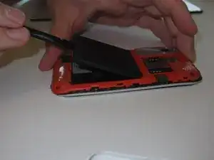
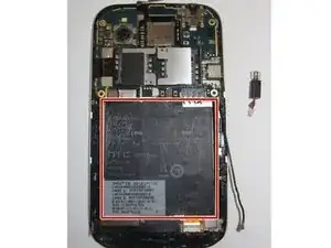
    • Lever the battery out from the bottom end first.

    • Do not bend or puncture the battery.

  3. WIlCGYDnPjv5VXJo
    WIlCGYDnPjv5VXJo
    2LJ1VADkNpWPf66i
    Y33LPJsHfbZcDZad
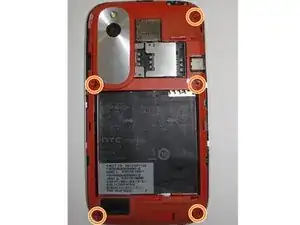
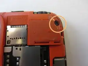
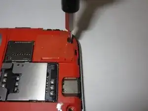
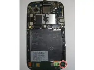
    • Use a Torx T5 screwdriver to unscrew and remove five 3.0 mm screws from the rear frame.

  4. 5iBYSrxNxjSAHvPp
    5iBYSrxNxjSAHvPp
    5Tkxhhd42vMuIYQl
    iQknLDAvqCRCYlnX
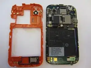
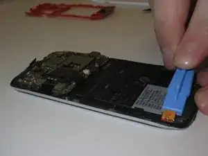
    • Use an opening tool or a spudger to gently remove the rear frame.

  5. uVLGQbqtXtJJkSlE
    uVLGQbqtXtJJkSlE
    KE4gvBofJjI4FXpq
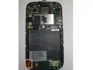
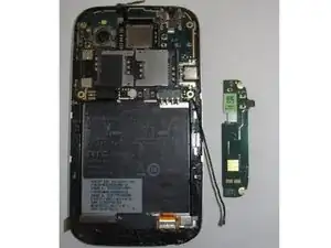
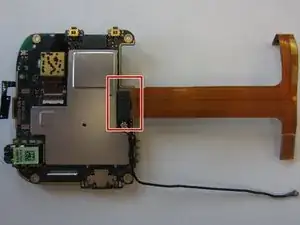
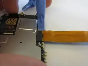
    • Remove the connector on left side of the Navigation board by unplugging/prying the orange ribbon.

  6. EGeQmiJSiYmEiNJt
    EGeQmiJSiYmEiNJt
    WrQWDIRUYSwgqsVO
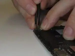
    • Gently unplug and remove aerial cable (black antenna) from bottom plug.

  7. BVrZuBkY2NoBUVAJ
    BVrZuBkY2NoBUVAJ
    hTo2DhuGcn2qIfVS
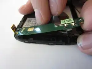
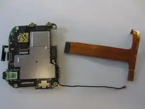
    • Nav Board will be stuck down by glue.

    • Pull gently from the right end of the board, being careful of its flexibility.

  8. jah4OfQoGaNVMJBF
    jah4OfQoGaNVMJBF
    RXRbWAigJRGaPB3D
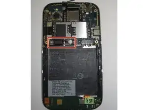
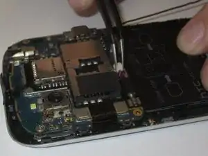
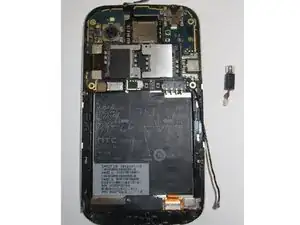
    • Unplug the vibration motor shown from the white plug on the motherboard.

    • You will probably need tweezers to do this.

  9. vDcP3oW4COLn5QeN
    vDcP3oW4COLn5QeN
    PfMWNrH2R4bT2eON
    • Gently remove the motor from its housing in the phone’s chassis.

    • The easiest way to do this is to lever the motor out by its rotating end using the tweezers.

  10. ikGorcecJnXwJarh
    ikGorcecJnXwJarh
    TttxWIJrEkgq6mHa
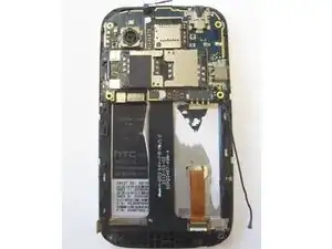
    • Remove the black information sticker if this is the first time opening the handset.

  11. jK4cSQ4cacEuxGTT
    jK4cSQ4cacEuxGTT
    tJgEUicEqEYdxcbk
    YxIu26lNcRoumxJC
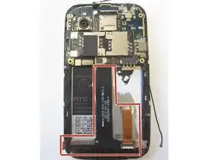
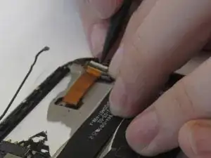
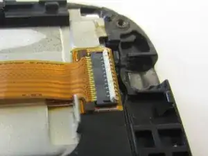
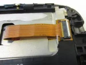
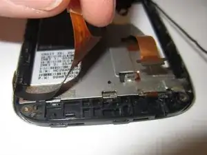
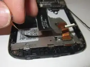
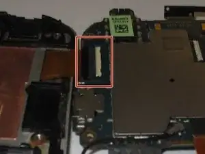
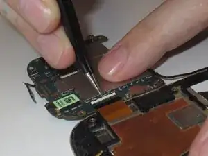
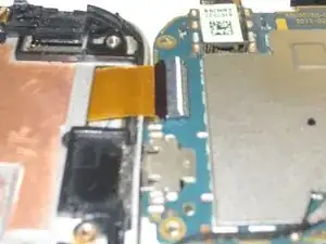
    • You should now see a black ribbon cable, which was connected at the left to the Nav board, and on the right, to a gold ribbon cable which goes to the screen.

    • Unlock the gold ribbon cable connecting screen to logic board by lifting the locking tab at the back of the socket.

    • For this you may wish to use a spudger or tweezers.

  12. c16kmb51jheruvjN
    c16kmb51jheruvjN
    rS6OjTAixUvmAKyE
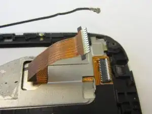
    • Disconnect gold ribbon cable connecting screen to logic board by pulling cable out gently.

  13. GMKtSQqOXUyrk2CT
    GMKtSQqOXUyrk2CT
    UboCihY5tJy3EkXW
    xGwggrcuQOeI2qt1
    • Gently unstick black ribbon cable from the chassis.

  14. pwRybxIT1Kc4pUIn
    pwRybxIT1Kc4pUIn
    d4ihPo2JUUKlmaGJ
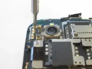
    • Unscrew the 2mm silver screw from top left.

    • Use a Phillips PH00 Screwdriver for this.

  15. GrJROHjwNFECwF1J
    GrJROHjwNFECwF1J
    pKcViCH6hWsZolhk
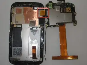
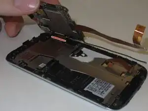
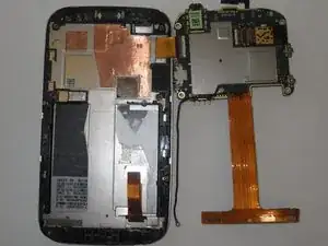
    • Gently pry logic board from the casing by lifting the left side up, as if there was a hinge on the right, folding it over the right edge where you will see a gold/orange ribbon cable.

  16. trhPfkjHYVdIyCQF
    trhPfkjHYVdIyCQF
    TMBeBRiwBEGL5acw
    uXxrUfSKYiJFMfhB
    • Remove the gold ribbon cable by lifting tab at the back of the socket, using a spudger or tweezers.

  17. ELEs2CKxaychKpAA
    ELEs2CKxaychKpAA
    AJB3BBUwRms5RwK5
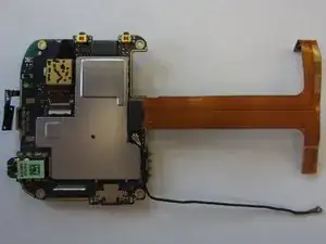
    • Gently pull the logic board to the right and it will disconnect from the chassis.

  18. yppTgsmRXdB2YjHW
    yppTgsmRXdB2YjHW
    6wPocFiwHLeKGGnD
    1IMTA5G34c2Zmxb2
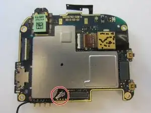
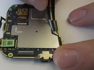
    • Noting that the rear side of the black ribbon cable is gold, use a spudger or an opening tool to gently disconnect it from the motherboard by levering it up at the right side

  19. d3U4RaxChGi4CgcN
    d3U4RaxChGi4CgcN
    WnUDNSr1egAQP1j6
    nJTvxZ5JFhtEXI5e
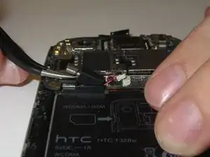
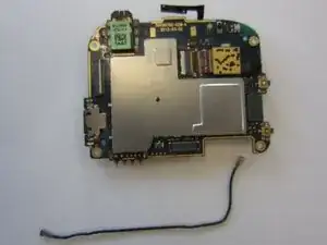
    • Gently unplug and remove antenna cable (black antenna) from socket beside the ribbon cable

    • If you lack usable nails, you will need tweezers

  20. lPqMqPbflH2REKRR
    lPqMqPbflH2REKRR
    DamAHmlmgVHE3j5y
    llBSWeAIVSUQJjIN
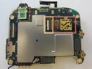
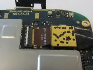
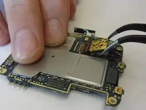
    • Locate the camera.

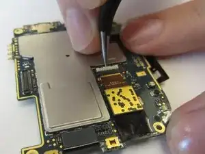
    • Lift the locking tab at the back of the connector for the camera using tweezers or opening tools.

  21. YecDqlfGXEUmWtjm
    YecDqlfGXEUmWtjm
    G512O5SvPC1GoHux
    IdCQI6VXjNEFNDSm
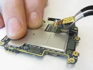
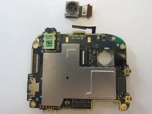
    • Preferably using tweezers, gently pull the camera assembly up from the motherboard, and away from the connector and the ribbon cable will slide out easily.

Conclusion

To reassemble your device, follow these instructions in reverse order.
William McCusker

Member since: 29/01/15

1096 Reputation

0 comments