Introduction

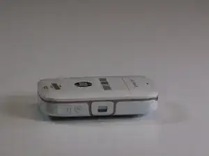
The USB port on the HP Sprocket 2-in-1 is a micro-USB port. The removal of said port will involve navigating and detaching numerous small and delicate ribbon cables. Be sure to avoid aggressive movements while completing the guide to avoid taring connections to other vital components.

  1. hCyBSsoMjmXCZ3qA
    hCyBSsoMjmXCZ3qA
    OAkKqxufKbWRHGun
    • Remove the back cover and any printer paper inside the device.

  2. bhsgjmJU1kNZLSZT
    bhsgjmJU1kNZLSZT
    aG6DSbNjgRu1AC6h
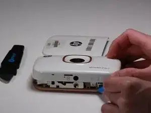
    • Using the Jimmy, slowly pry open the outer edge of the remaining white plastic on the back.

    • Remove the plastic from the device once it lifts out freely.

  3. wRRp3fHUFsD5GIhf
    wRRp3fHUFsD5GIhf
    YCJLugEZk5UBJPts
    aWr1gTjBUAXHuGsO
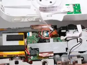
    • Remove two 2.5mm JIS #00 located on the small circuit board in view.

    • Use the Jimmy to remove the board after the screws have been removed.

    • Be careful not to crease or damage the ribbon cable.

  4. 4NAwOFqyvW2iCAyZ
    4NAwOFqyvW2iCAyZ
    VOhQSAUIUXtkkL4Z
    EI5NIO5rupiOngE1
    • Remove two 2.5mm JIS #00 screws from the translucent plastic bracket.

    • One will be located beneath the ribbon cable.

    • Remove the translucent plastic bracket by hand.

  5. YdmlFPiGlFe1eVod
    YdmlFPiGlFe1eVod
    DjyLgGFgO6RD3VsJ
    • Remove four 2.5mm JIS #00 screws from the beige casing.

  6. Exr1HSKE1mX3U2xw
    Exr1HSKE1mX3U2xw
    yaDUYMLsXHfkBiEN
    LeL4MKGxchUAfPdX
    • Use the iFixit opening tool to slowly work between the white and beige casing around the device.

    • Flip the device over and seperate the white casing from the rest of the device.

    • Be careful not to break the plastic while removing the case.

    • Gently remove the white casing as there is a ribbon cable connecting the two pieces.

  7. HQxeDUk1JFJArA2M
    • Carefully remove the ribbon cable that connects the flash to the outer casing.

  8. jX5nW6ChYAhqp44e
    jX5nW6ChYAhqp44e
    YAbUKeeUfHrquQse
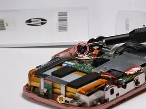
    • Use a JIS #00 screwdriver to remove a single black screw near the viewfinder.

    • Remove a single silver 2.5mm JIS #00 screw near the USB port of the device.

    • Carefully remove the metal bracket.

  9. kZbrikHQhSerIdHD
    • Work the battery free from the device with the iFixit opening tool.

    • Carefully disconnect the battery from the board.

  10. ECIfpLSWTQPeWKq4
    ECIfpLSWTQPeWKq4
    xrNjsEJ4WTNKArWf
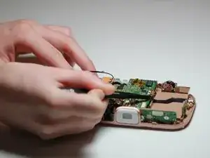
    • Using the metal tweezers, remove the ribbon from the motherboard.

    • Remove two 2.5mm Japanese Industrial Standard (J00) screws on each side of the USB port.

  11. BprJKbaOINkWwskr
    • Remove the SD Port with metal tweezers.

    • You can now replace the SD port with a new one.

Conclusion

To reassemble your device, follow these instructions in reverse order.
Paulo Warren

Member since: 05/02/19

458 Reputation

0 comments