
Introduction
The motherboard is the brain of the printer, so if anything goes wrong with it, your entire printer becomes worthless. In order to access it, you will need to remove the side panel.
To remove the motherboard, you will need to remove several connectors, so a set of small hands will be helpful. You will also need a screwdriver to remove the four 8mm T9-Torx screws securing it in place.
Be sure to ground yourself and the device when removing the motherboard and its connectors so short circuits do not occur.
Be sure to set a space aside for the screws so you don't lose them.
-
-
Turn off the printer and remove the power cable.
-
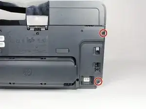
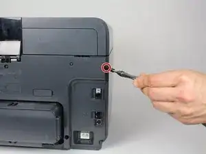
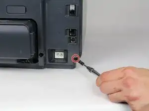
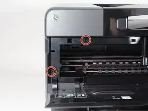
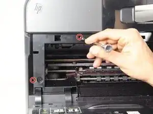
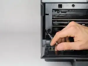
Remove two 13mm T9 screws using a T9-Torx screwdriver. Turn counterclockwise until the screws are released.
-
-
-
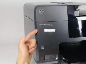
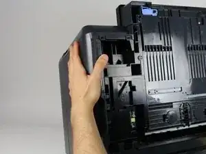
Open the front door by placing your finger on the indented groove on the left side of the printer and pulling down
-
-
-
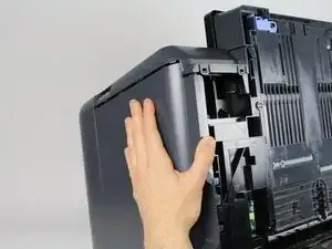
Gently remove the left side panel by placing your palm flat against the surface and pulling down.
-
-
-
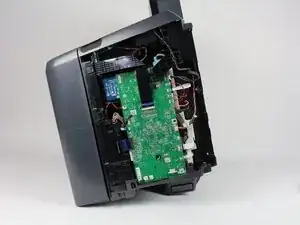
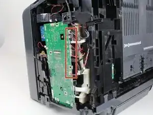
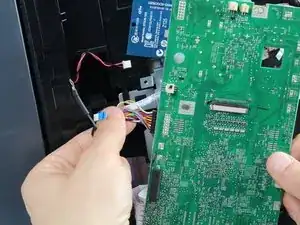
Remove all connectors by gripping the plastic housing the wires and gently pulling outward until they disconnect.
-
-
-
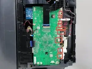
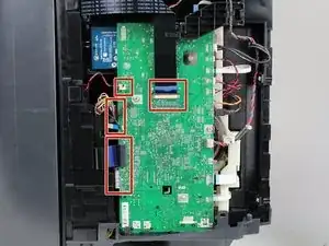
Gently disconnect connectors by gently pulling on the plastic housing until they release from the motherboard.
-
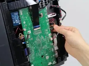
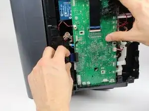
Gently grasp the ribbon connectors so they do not bend by gripping top and bottom and lightly pulling until they release from the motherboard.
-
-
-
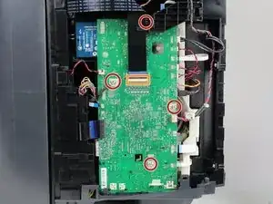
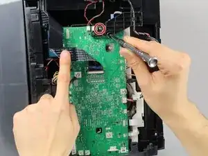
Remove the four 8mm screws by using a T9-Torx screwdriver, turning counter-clockwise until released.
-
Lift the ribbon connector in the center of the motherboard away after it has been disconnected to access the last screw.
-
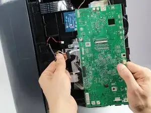
Move the plastic piece away from the motherboard before removing it.
-
-
-
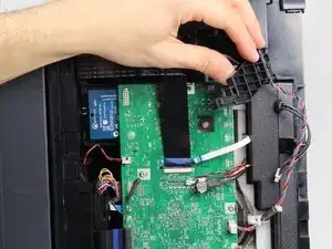
Release any remaining connectors from the motherboard by gently pulling away until they break free.
-
Remove the motherboard.
-
To reassemble your device, follow these instructions in reverse order.
One comment
Dear Sir,
could you send me the electronic schematics for the HP 8610 motherboard and side panel . I have a problem with the switching on of the unit
thank you
Stephen Proverbs
s_proverbs@caribsurf.com
Apparently screws are T10 not T9. T9 driver/bit works, but you'll slightly damage the screw. I use a T10 now.
dbovey -