Introduction

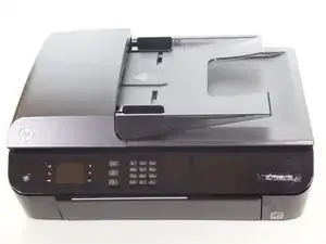
The scanner head is necessary for copying and faxing. Follow the guide to replace this crucial part.

  1. DJgFTt4yRQCqXsSe
    DJgFTt4yRQCqXsSe
    Nnfrfw5THPMk6jwt
    EiKCCi1NbTCn3TdG
    • There is a hidden screw underneath the model sticker on the front panel.

    • Peel the model sticker off the cover.

    • This will expose the T10 screw securing the panel.

  2. 4v4mEgJUaYCaIeCx
    4v4mEgJUaYCaIeCx
    VDrxbHyoFonAO6U6
    XnNWpixCAShBmd1V
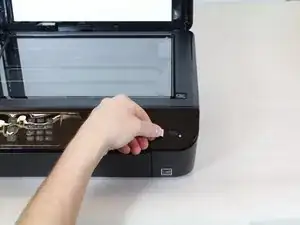
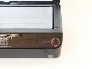
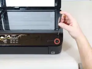
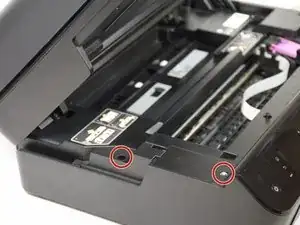
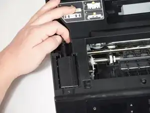
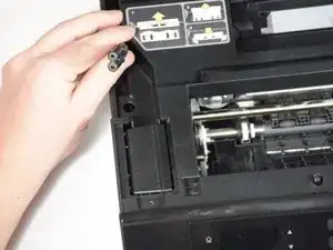
    • Remove the single 12mm-T10 screw securing the front panel to the printer body.

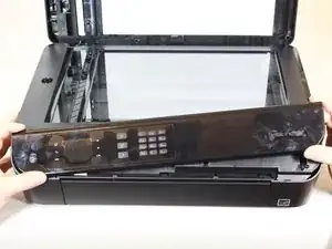
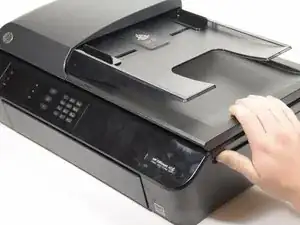
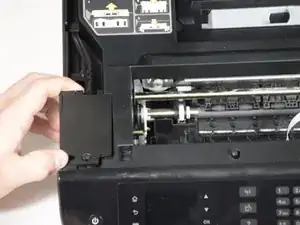
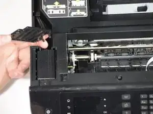
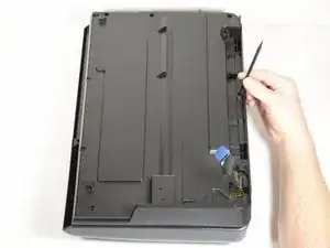
    • Loosen the panel cover from the printer body.

    • There is a ribbon cable connected to the backside of the cover. Disconnect the cable before separating the panel completely.

    It would be good to note that to “loosen the panel cover from the printer body,” the procedure is to:

    1. Take out the screw

    2. Slide the panel cover gently to the right until it stops (1/4 inch)

    3. Slide the panel cover upwards thus lifting it from the holding tabs

    4. Remove panel cover

    Otherwise it makes it seem like steps 2 and 3 are not necessary which could cause someone to use excessive force to remove the panel cover.

    Gordon Rodgers -

  3. r2miiqYmwZpmrjAJ
    r2miiqYmwZpmrjAJ
    UjN2CUETcKVQNHQa
    qFkyxlvBgySDfUmg
    • Gently remove the No-Fuss ribbon cable from the front panel.

  4. BSBVxKxK1IcWlyFc
    BSBVxKxK1IcWlyFc
    bGhgbMRQQEFJ36Mw
    jFC5EImdBkkBUajH
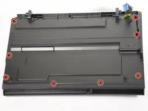
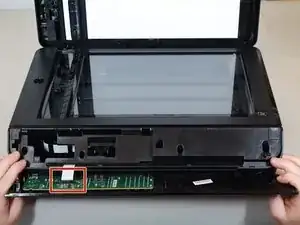
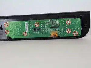
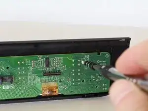
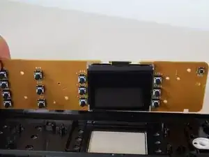
    • Remove the seven 8mm screws using the Torx T6 screwdriver.

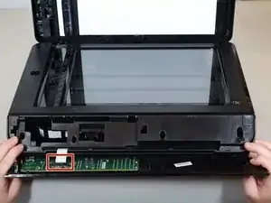
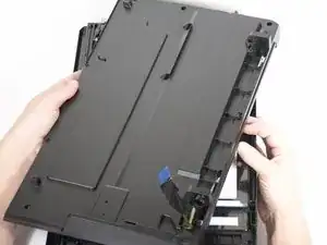
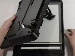
    • Remove the motherboard from the front-panel housing.

    • The LCD display is on the opposite side.

  5. orgEWZqXWfDlekGO
    orgEWZqXWfDlekGO
    pfBVdvVXVl1wCADY
    iVEyafX2NOfYarUC
    • Lift the hood of the printer.

  6. iiMiYEHKDFClQvxF
    iiMiYEHKDFClQvxF
    QCgnUCCKyavq5gRU
    UvCmTK3FX1XoWChs
    • Remove the two T10 11mm screws.

  7. gKrRmW2HbThQvJ1r
    gKrRmW2HbThQvJ1r
    JJMTNWDuhNxotcAU
    KqeWQcHae2US3jlT
    • Remove the panels covering the power brick and cord.

  8. GTQXDRVuqrTYS6ef
    GTQXDRVuqrTYS6ef
    actPvqFHsywbLTMm
    • Remove the cord from the power supply.

  9. G2kgnFrjAKEoFK3V
    G2kgnFrjAKEoFK3V
    bIuIgwApHdUCKVk5
    6CvxQqYhrDFtL1jx
    • Slide the power supply out from the chassis.

    • The power supply is still attached; don't pull too quickly.

  10. KM2GXqsfvFGW3TJ1
    • Remove final cable from power supply.

    What if it isn't the power module what if its the power button it self. Because where the module is connected I see power is on

    George Munoz -

    Thank you for this concise post. How does one know it is the power supply to change? I hear a humming sound when I plug in (after 30 second button push reset), but no display or lights.

    CV Play and Grow -

  11. JwtQaV4MOlSvYFO2
    • Remove eight T10 1mm screws from the top hood of the printer.

  12. Y6uVjZIDQyUxDCLa
    Y6uVjZIDQyUxDCLa
    ZTiC54BKHCyCVD1B
    G4civIRCZAtyI3as
    • Use the nylon spudger to pry the tab.

    • Lift up the entire panel.

  13. 5YjOw1kPm6uEIc4P
    5YjOw1kPm6uEIc4P
    Hj2qIqi4JWJHmrvE
    PWuduyQcvxfPOROh
    • Lift and flip the entire panel.

    • Be aware of the scanner head attached to the panel.

  14. YYsOF2XnJIZgP6ht
    YYsOF2XnJIZgP6ht
    lKHlOm2DE6SGJXcO
    UN3L1WTNnFLGJ4Ay
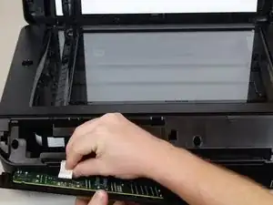
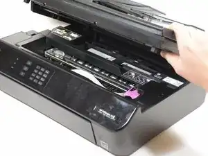
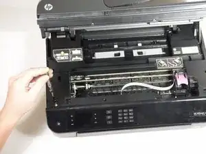
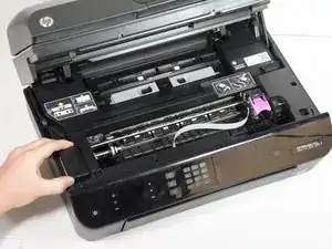
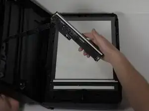
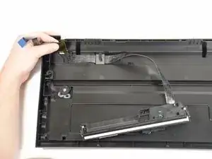
    • Start with the scanner head in place.

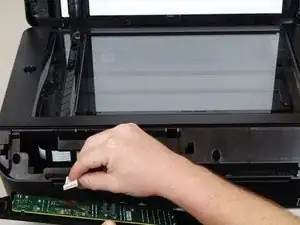
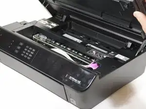
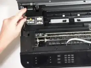
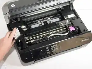
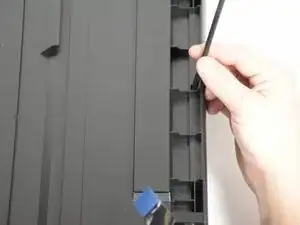
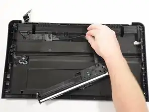
    • Unwind the ribbon from the track.

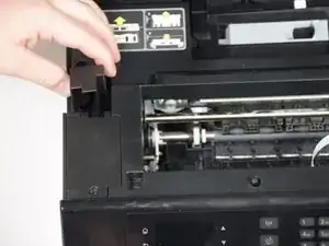
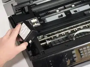
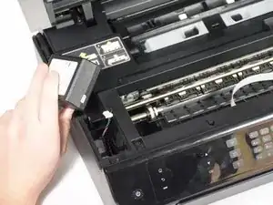
    • Detach ribbon completely.

Conclusion

To reassemble your device, follow these instructions in reverse order.

Maya Willis

Member since: 24/01/18

415 Reputation

0 comments