Introduction

This guide is used as a prereq to other guides.

  1. PWPq3BGFZMsxuaVD
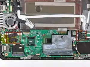
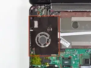
    • If present, remove the large piece of black adhesive film covering the area around the fan.

  2. SJDchHvkLRh2RSnQ
    SJDchHvkLRh2RSnQ
    KGAuLv5MxsxADX2h
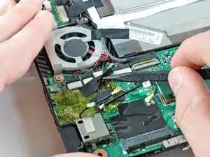
    • If present, remove the pieces of black cloth tape securing the antenna cables to the motherboard.

    Prepare steps 24-22 on reinstallation, so you know where to line up the tape. These steps go somewhat together on reassembly.

    Matthew -

  3. MNFOB55nVROsMh43
    MNFOB55nVROsMh43
    sRD1jpbiWpZmLI1m
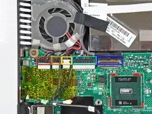
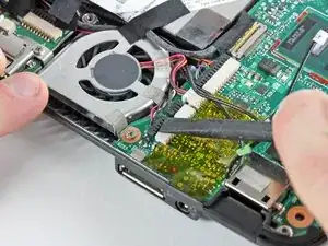
    • Use the flat end of a spudger or your fingers to disconnect the following cables:

    • Speaker cable

    • Microphone cable

    • Fan cable

    • Power cable

    • Display data cable

    • Do not lift the connectors up as you disconnect them from the motherboard. Push the connectors out of their sockets parallel to the face of the logic board toward the display assembly. Use extra care when disconnecting the display data cable, as its connector and socket are fragile.

  4. r53DmUKvERauGEYj
    r53DmUKvERauGEYj
    Hk24wGpyopfXFMi3
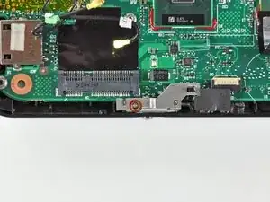
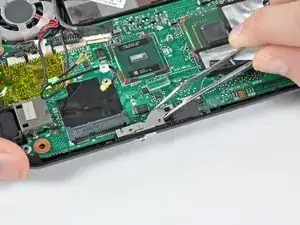
    • Remove the 2.5 mm Phillips screw securing the power switch lever to the lower case.

    • Use a pair of tweezers or your fingers to lift the power switch lever out of the Mini 1000.

    Bend the levers in step 35+36 slightly before reassembly, so that the screws push them down tighter. The levers appear to slacken with age.

    Matthew -

  5. RCyTF45uDFWZLnmD
    RCyTF45uDFWZLnmD
    MyUhDmTcWEaDmxjY
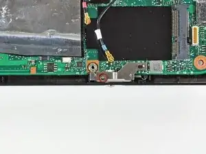
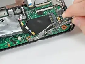
    • Remove the 2.5 mm Phillips screw securing the wireless on/off switch lever to the lower case.

    • Use tweezers or your fingers to remove the wireless on/off switch lever from the Mini 1000.

  6. Gm4DXpGqPFH6LLoC
    Gm4DXpGqPFH6LLoC
    xpx2J2R5ySoVKCD6
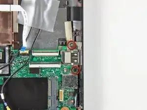
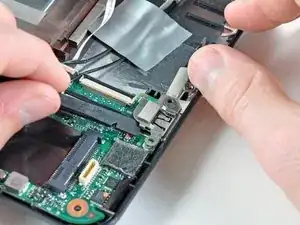
    • Remove the two 3 mm Phillips screws securing the USB bracket to the lower case.

    • Pry up the USB bracket and remove it from the motherboard.

  7. 1DoBbAUjmYoXtPoT
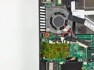
    • Remove the single 4.5 mm Phillips screw securing the motherboard to the lower case near the fan.

  8. WdesHFdUyidE6Zcj
    WdesHFdUyidE6Zcj
    VUDjm1MWHNFcPhTL
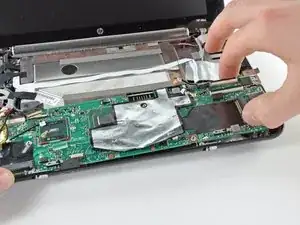
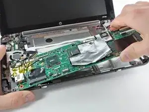
    • Carefully lift the motherboard from its right edge and remove it from the lower case, minding any cables that may get caught.

    When reinstalling, insert left side first, slightly pry right side of case to get motherboard to seat.

    Matthew -

    There's another four wire connector on the back of the board on the right, connected to an unused item that appears to be USB (but that would have five wires, right?)

    Matthew -

Conclusion

To reassemble your device, follow these instructions in reverse order.
Walter Galan

694047 Reputation

0 comments