Introduction

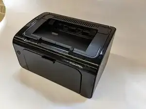
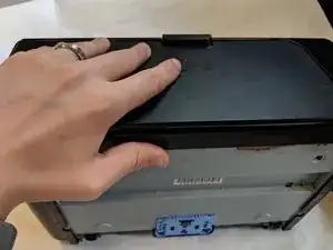
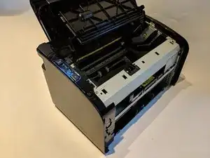
These steps will show how to replace the motherboard from the printer. This guide may be used if the printer is experiencing systematic errors, was short circuited, or has issues connecting to devices.

  1. nvvMSaTB6LhY5O2H
    nvvMSaTB6LhY5O2H
    3KviFtWAqEL635lO
    uu4hNTDNZGRJRLDi
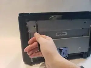
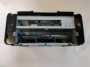
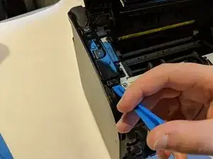
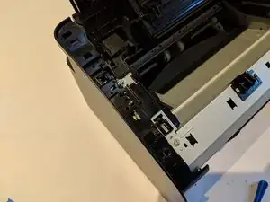
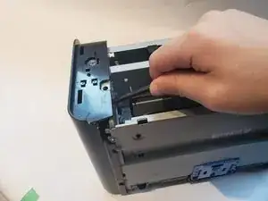
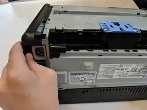
    • Flip printer on it's back. Using the plastic spudger, pry off front panel. There will be two main points to focus as shown.

    • Pry carefully to not break any plastic.

    my two main points were precisely under the rubber feet, they were surprisingly difficulty to dislodge.

    Peter Taffs -

  2. NIJMZwQvtwImYNTv
    NIJMZwQvtwImYNTv
    o45c6jPQv6VEfxOT
    • Now that the pry points are free lift up the front panel.

  3. Kb1TJdCvROU1tin3
    Kb1TJdCvROU1tin3
    yFsUkKP1quiWB3DI
    • Unscrew the #1 Phillips screw 6mm on the back of the printer.

  4. 1lbqCf2kFUKLQfot
    1lbqCf2kFUKLQfot
    1bZyNkZ2GOV5gtFC
    MN6Ci2JNFpCkmXYH
    • Using the plastic spudger, remove the button housing from the top left of printer.

    • Pry carefully to not break any plastic.

  5. FgdkSShn5UXSHuMn
    FgdkSShn5UXSHuMn
    ThHVxqNGnsX6JOE6
    • Once the housing is removed, remove the three buttons.

  6. LIY5HWgXD2ATV6L2
    LIY5HWgXD2ATV6L2
    Y5hnKsKNSw6NrvBu
    VyKBNHRfYAkNJXf5
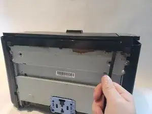
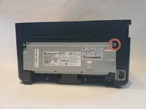
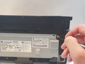
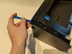
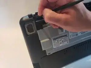
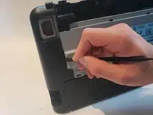
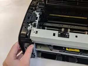
    • Use the plastic spudger to remove the side panel. There are three main prying points as shown.

    • Pry carefully to not break any plastic.

    mine had a PH2 screw on the printer back thru the side panel into the aluminum serial plate/back, placed in the 2nd and third picture in the tab with a round screw hole and square locator hole. Critical clips were center back, center top and center bottom, and two points on the front.

    Peter Taffs -

    edit, i see the screws talked about in step 3. sorry.

    Peter Taffs -

  7. 6qBMx5RC5Ogb3lew
    6qBMx5RC5Ogb3lew
    5bcJjmhwWYb11OFr
    • With all pry points free, remove the side panel.

  8. U2YKE4nYMrL6dOdH
    U2YKE4nYMrL6dOdH
    KnEPHsltHRnPwKdD
    1MWgZkFJGViUtAsK
    • Remove three #1 Phillips 6mm screws with the #1 Phillips screwdriver.

  9. JfFm1NjAsy3ix3uc
    JfFm1NjAsy3ix3uc
    A5tnePHKDuhMTUQ2
    mnkIyDMXvMjOwBqw
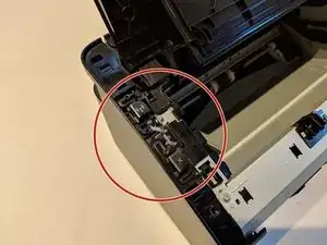
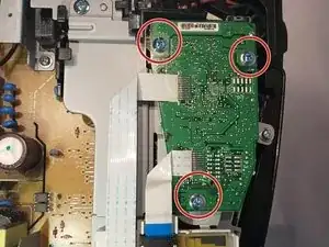
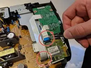
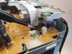
    • Using a pair of blunt nose tweezers, disconnect both ribbon wires.

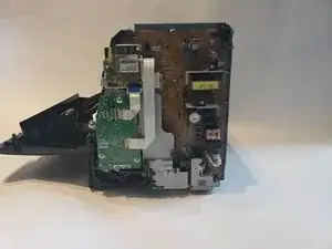
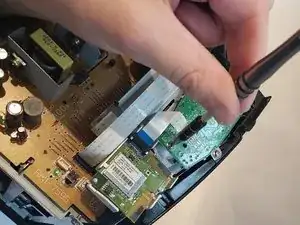
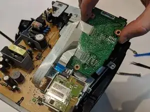
    • With both ribbon wires removed we can lift the motherboard out of its housing.

    • There is a little black notch holding the motherboard down by the thumb in the final picture.

    • Be careful pulling, as ribbon wires are very fragile.

Conclusion

To reassemble your device, follow these instructions in reverse order.

Jerome Etten

Member since: 04/10/18

709 Reputation

0 comments