Introduction
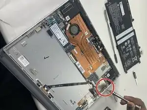
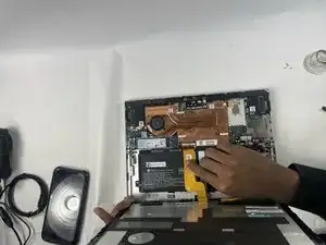
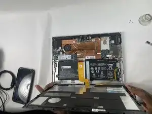
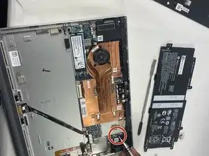
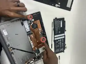
One of the primary reasons to upgrade your motherboard is a new, faster CPU, or if your current motherboard is damaged. This guide will help you replace your HP Elite x2 G4 motherboard. To begin the process, we recommend watching this video.
This guide contains step by step instructions to complete the installation. There are no special skills required to complete this replacement. There are only two tools needed for installation a T5 Torx Screwdriver, and a Phillips #0 Screwdriver. The following are hazards that should be avoided during installation:
Short circuit: Ensure that all cables are securely connected, screws are tightened, and the motherboard is properly fitted into the case.
Physical Damage: Mishandling during installation can cause physical damage to the motherboard. Avoid bending pins, damaging ports, or placing the motherboard in contact with unintended objects.
Tools
-
-
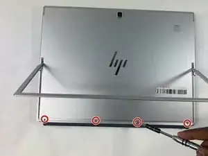
Open the kickstand.
-
Remove the four 3 mm T5 Torx-head screws that secure the display assembly.
-
-
-
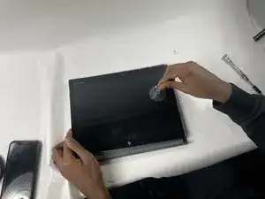
Use a suction sup to carefully detach the display assembly in the following order: top-right corner, top-left corner, bottom-right corner and bottom-left corner.
-
-
-
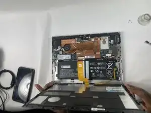
Slowly lift the display panel until you have access to the battery connector on the motherboard (approx. 90 degrees).
-
-
-
Disconnect the battery cable from its motherboard connector.
-
Remove the tape that covers the touchscreen and display panel ZIF connectors.
-
-
-
Disconnect the touchscreen ribbon cable from the motherboard.
-
Remove the display panel assembly.
-
-
-
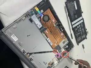
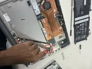
Lift the USB bracket off of the motherboard and remove it.
-
Remove the four 2 mm Phillips #0 screws that secure the motherboard.
-
-
-
You would then disconnect the following cables from the motherboard:
-
- Left and right speaker cables.
-
- Volume button board ribbon cable.
-
- Left and right hall sensor ribbon cables.
-
- Fingerprint reader ribbon cable.
-
- WLAN antenas.
-
- SIM cardboard ribbon cable.
-
- POGO ribbon cable.
-
To reassemble your device, follow these instructions in reverse order.
