Introduction

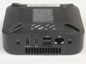
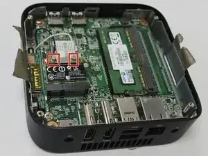
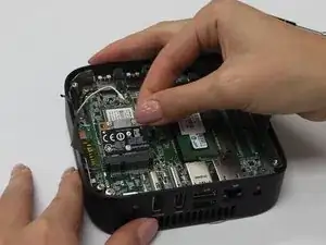
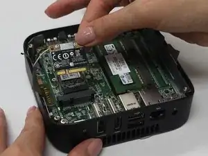
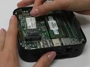
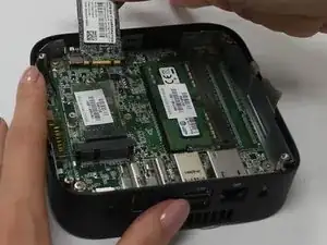
If the System Board of your HP Chromebox is damaged, it is easy to replace. This guide will take you through the steps of replacing the hard drive. For this guide, you will need the Phillips #1 screwdriver .

  1. AYdDaZtUbyrLvOIg
    • Before removing the bottom cover, ensure that your computer is powered down and ensure that all external devices are disconnected. If you are unsure whether the computer is off or in hibernation mode, turn the computer on, then shut it down through the operating system.

    • Position the device upside-down on a flat, level surface with the USB ports facing you.

    both for the cover replacement and shield replacement

    Ian Stoffel -

    For the hard drive replacement, a longer times should be indicated. for the WLAN replacement 15 minutes is indicated, but for the hard drive replacement, which can only be done after the WLAN replacement, the time is listed as 10 minutes.

    Ian Stoffel -

  2. Pw2kb1A6TA5mVHo5
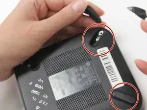
    • Using your metal spudger, lift and remove the 4 rubber “feet” from each corner.

  3. uQV3EtuDrcQobMCE
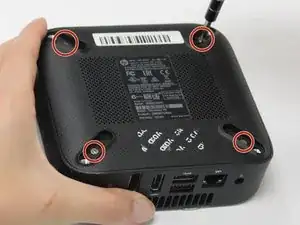
    • Using your Phillips head screwdriver, remove the four Phillips M2.5×4.0 screws that secure the bottom cover to the computer. In this step the usage of the magnetic mat will be helpful to keep up with the screws.

  4. q22CfOuSZgctm5md
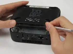
    • Insert the flat end of your metal spudger under the bottom cover near the USB ports, then pry the bottom cover off the computer.

  5. hKXl2knOdHNbfsbW
    • Lift the two pieces of mylar tape from the bracket.

    Flag: Confusing Text

    in steps 5 and 6 it seems the bottom shield is called a bracket, so by using 2 different names it’s making it seem like we’re missing a piece/part

    Ian Stoffel -

  6. UedXf4etMAiMDjXM
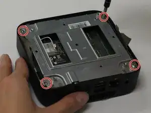
    • Using your Phillips #1 screwdriver, remove the four Phillips M2.5×4.0 screws that hold the shield in place.

  7. 2EIpmVHmZJRAhmIL
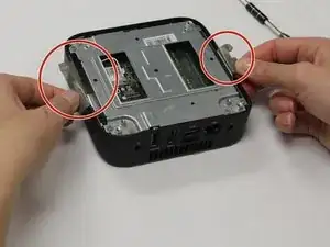
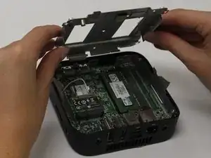
    • Insert your spudger into the gap between the bottom shield and the ports and gently pry to lift and remove the shield.

    another picture of where to insert the spudger may be helpful. which ports are you talking about?

    Ian Stoffel -

    Flag: Needs More Images

    another picture of where to insert the spudger may be helpful. which ports are you talking about?

    Ian Stoffel -

    Flag: Missing Details

    a note step on paying attention to how the shield is positioned before removing it may make reassembly easier

    Ian Stoffel -

  8. XBCwj3BTLTiNvq6B
    XBCwj3BTLTiNvq6B
    BCLQTpNTLH1AwWwR
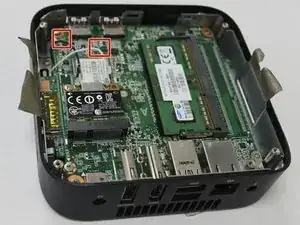
    • Disconnect the white and black antenna cables from the module.

    Flag: Markup Mishap

    iFixit has in their Milestone 3 instructions to not use arrows. we recommend either a box over each connector or a rectangular box over the 2 instead

    Ian Stoffel -

  9. hAQKpL32fUQ2yg4Q
    hAQKpL32fUQ2yg4Q
    qVwJhlMWD1euqq1a
    DPCsY6M22hWHbMPV
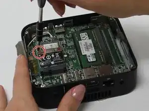
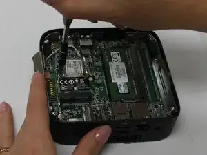
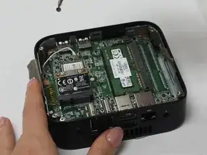
    • Using your Phillips #1 screwdriver, remove the M2.0×3.0 screw from the upper left corner of the module.

    • Once the screw has been removed, the module will tilt up.

    Flag: Needs Better Images

    we don’t think picture 2 is needed at all.

    picture 3 doesn’t really show how the module has popped up. the angle is wrong to make it obvious

    Ian Stoffel -

  10. UklaUJ2gnDOitDJs
    UklaUJ2gnDOitDJs
    BXGaIJp26C244O1C
    • Remove the WLAN module by pulling it away from the slot at an angle.

  11. va5vaXZeyWIPT5ea
    va5vaXZeyWIPT5ea
    t54wFZCSaWSAJUIZ
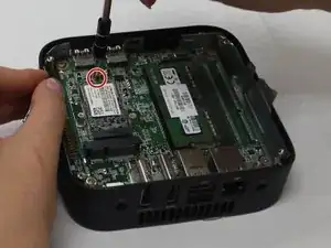
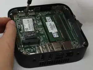
    • Remove the Phillips M2.0×3.0 screw.

    • The hard drive will tilt up once the screw has been removed.

    Flag: Missing Details

    more information about which screw and where it’s located could be helpful. if you don’t look at the pictures there’s no way to tell which screw is indicated or which component is the hard drive

    Ian Stoffel -

  12. cLSWoPZCsEhITAYh
    cLSWoPZCsEhITAYh
    Pb4hOeYpdRYPwnQl
    • Pull the hard drive at an angle to remove it from its slot.

  13. WkCM1sIFx3hOsmIU
    WkCM1sIFx3hOsmIU
    IJcaEXAQkQjPkFkw
    fpkT4pcHHk3cR1Oc
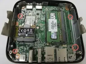
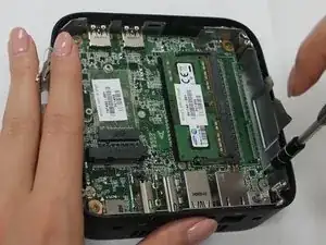
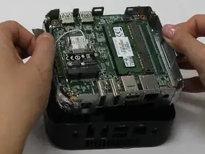
    • Remove the four Phillips M2.5×4.0 screws by using the Phillips #1 Screwdriver, that secure the system board to the computer.

    Flag: Needs Better Images or Missing Details

    picture 1 doesn’t show the screws very well or at all. either a note that the screws are under the green main board or a picture more from above the unit so the screws are easier to see is needed

    Ian Stoffel -

    Flag: Missed a Step

    this may not apply, but it’s not likely that a stick of RAM comes with a new system board, and so a short step to remove the RAM so it can be installed on the new system board may need to be considered.

    Ian Stoffel -

  14. aPXaCCPiq4CsFSqh
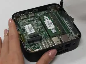
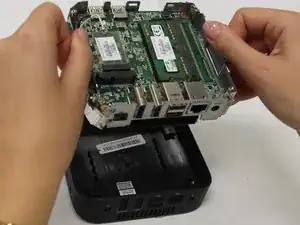
    • Use the mylar tape to lift the system board out of the computer.

    It looked good to me, too. one thing that tripped me up was the screw sizes. as a techie type person i felt i understood what you meant (metric 1.0mm by 4.0mm) but it looked a bit too jargony to be clear to someone not familiar to standardized screw sizes. if there’s a way to put this in clearer every day wording that might be helpful. personally i thought iFixit’s insistence on listing screw sizes was a little over the top (who’s going to actually measure if that’s a 1.2 or a 1.5 mm screw?). you guys had a tough unit but i think you did great with what you had.

    Ian Stoffel -

Conclusion

To reassemble your device, follow these instructions in reverse order.
Ashley Marvin

Member since: 06/09/18

685 Reputation

0 comments