Introduction
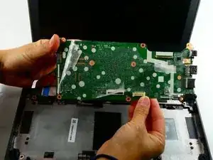
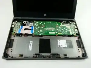
The motherboard is the primary piece of circuitry that helps keep your laptop running. After troubleshooting through the possible issues with the motherboard and determining that it needs a replacement, you can follow these steps in order to accomplish that goal. This guide will walk you through the steps of replacing the motherboard in your HP Chromebook 11 G8 EE.
Note that there are many symptoms to a failing motherboard such as a loose connection that is a lot less costly than a replacement.
Tools
-
-
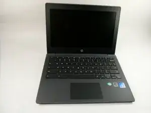
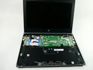
Flip the device over and open the lid.
-
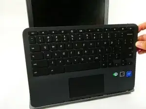
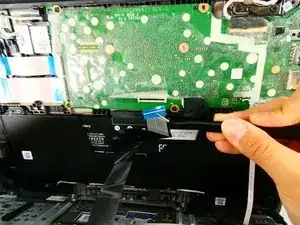
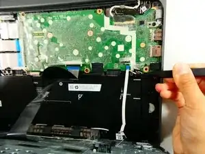
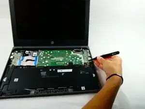
Use a plastic opening tool to pry the keyboard assembly away from the bottom case, prying around the perimeter until it fully separates.
-
Lift the keyboard assembly from the laptop towards you, away from the screen.
-
-
-
Lift the keyboard ribbon lock bar and use tweezers to disconnect the keyboard ribbon from the motherboard.
-
Lift the lock bar and use tweezers to remove the touchpad ribbon.
-
Remove the keyboard.
-
-
-
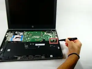
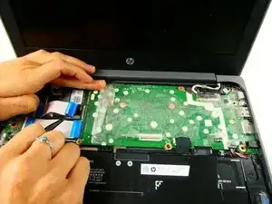
Peel back the film over the speaker's motherboard connector.
-
Disconnect the speaker cable from the connector on the motherboard.
-
-
-
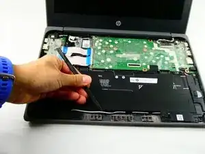
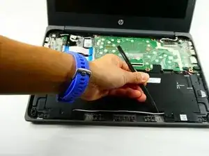
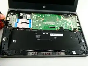
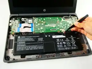
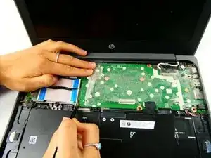
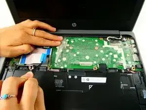
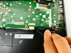
Disconnect the battery cable from the motherboard by pulling the connector straight out of its motherboard port.
-
-
-
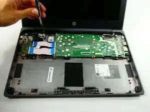
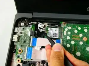
Unscrew the single screw securing the Wi-Fi card/cover using a Phillips #1 screwdriver.
-
Remove wireless antenna cables from the module using tweezers.
-
Pull the Wi-Fi card out from its motherboard port using tweezers.
-
-
-
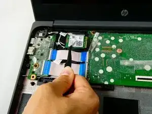
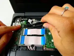
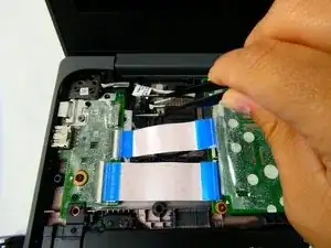
Flip the two black lock bars on the ZIF connectors using tweezers.
-
Disconnect both ribbon cables from the motherboard using the tweezers.
-
-
-
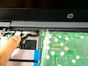
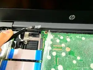
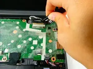
Peel back the film and lift the lock bar on the display panel cable with tweezers.
-
Disconnect the display panel connector with tweezers.
-
-
-
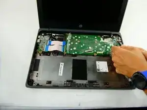
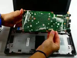
Remove the six 3.5 mm screws with a Phillips #1 screwdriver.
-
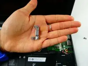
Lift the USB-C bracket off the motherboard.
-
To reassemble your device, follow these instructions in reverse order.
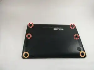
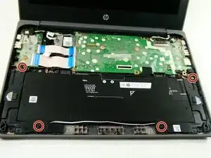
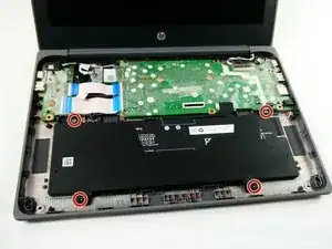
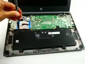
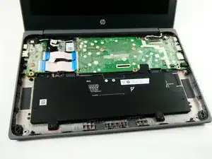
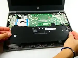
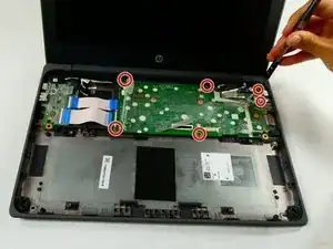
Is it possible that the screw location diagram is incorrect? On my g8 ee it seems that the longest screw (the orange 8 mm?) Goes closest to the screen hinge and the other 4 screws are identical size (the 7mm?).
In the diagram, the longest screw (orange) is shown as being located farthest from the screen hinge. But I've also seen a YouTube video possibly corroborate this guide's screw information, differing from the 2 G8 EE models I checked in person.
A X -