Introduction

Use this guide to replace the motherboard in your GoPro Hero+ LCD.

  1. veBKex3PJoGbJNVs
    veBKex3PJoGbJNVs
    dtVmUMJSjQZmCOoM
    • Be sure to power off the GoPro before you start disassembly.

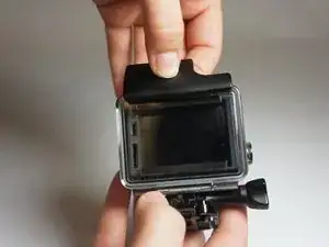
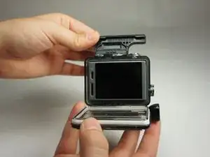
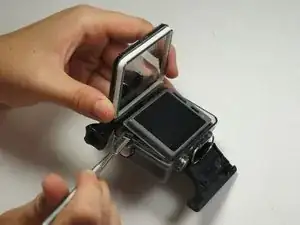
    • Pop up and pull back on the clip to remove the screen cover and expose the back panel with the touchscreen.

    No parts required! What about the microSD/Micro USB assembly!!!! where to buy?!?!

    WPN -

  2. nn5XBlqcVOVNPP35
    nn5XBlqcVOVNPP35
    h1LTojlumdaY3BTv
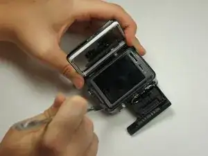
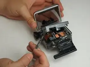
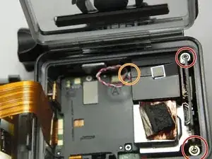
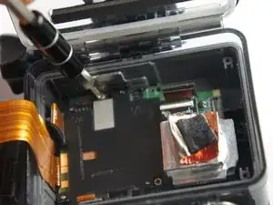
    • Use the metal spudger to pry around the perimeter of the panel.

    • Pry the panel upwards by inserting the metal spudger into the corner crease between the panel and camera shell.

  3. AHpaE3JECUFDpUiR
    AHpaE3JECUFDpUiR
    rR5MGNqM2DEy5rTb
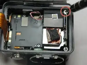
    • Pry around the panel to ensure it is not attached to the device.

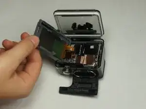
    • Move the panel to the side so you can access the internal components.

    • The panel is still attached to the rest of the device with a ribbon cable, so be sure to not tear or damage the cable.

    а где можно купить вот этот шлейф соединяющий дисплей и плату.???

    Александр «ivkadre» Карпенко -

  4. 1K5lYwMj6TGOsqXx
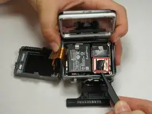
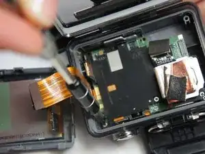
    • Peel back the rear panel ribbon cable that is adhered to the battery until it is completely separated from the battery.

    • Be careful of metal contacts on strip; they can be sharp.

  5. vA1JyBxlaDHAZoyU
    • Using tweezers, peel off the copper tape on the right side of the battery.

  6. RwG5seTxgUItMwfq
    RwG5seTxgUItMwfq
    sHDYJeDJ2Lt3XhCl
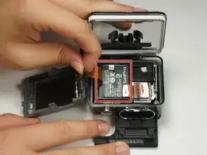
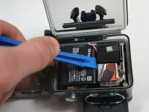
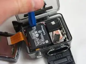
    • Place the plastic opening tool at one of the edges of the battery then pry until the battery is removed from the GoPro.

  7. WXBrGjWnwTqtCqYE
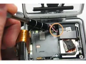
    • Use a pair of tweezers to disconnect the battery connector from the motherboard.

    • Gently pull the battery off the motherboard. Pulling vertically off the motherboard will give a clean release.

    Lift the battery connector straight up.

    glenn tanner -

    hi what kind battery can replace for hero+?

    sherwin_0011 -

  8. jkj2rKFchNDjXfLu
    jkj2rKFchNDjXfLu
    3Uwc4ndlw6bWNVaD
    rZDhlx5IFsAuT1IO
    • Remove the two 6 mm Phillips #00 screws.

    • Remove the single 4 mm Phillips #000 screws.

  9. RLgDilYqRsekdEqm
    • Remove the image sensor from the camera.

    • You do not have to unplug the black box to remove the USB/SD chip.

  10. vwFOSAehEFanBSvy
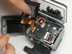
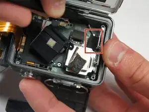
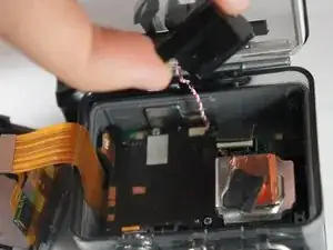
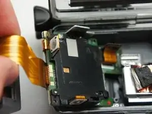
    • Grab the edge of the ribbon cable with the tweezers and gently pull until the cable is disconnected from the motherboard.

    • Be careful when removing the ribbon cable. You must pull gently or you can rip the ribbon off of its contacts.

  11. fA4GoJZBcNNiH4a3
    • Gently lift the microSD/Micro USB assembly up and out of the device.

  12. yGZSfahBRbGicECj
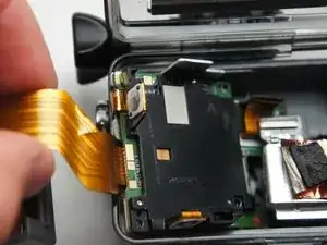
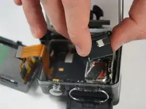
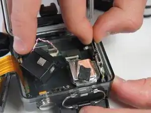
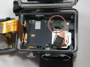
    • Use your fingers and gently pull out the sensor from the motherboard by slowly and gradually pulling up on the image sensor box.

    • Do not yank on the image sensor, it can rip out the wiring or damage the motherboard.

  13. daic4WFK1x6obnaR
    daic4WFK1x6obnaR
    vO5SNtDpefQN1Sdg
    HEA4rDWQJ6LXPIXm
    • Remove the three 4 mm Phillips #000 screws securing the motherboard.

  14. MYSWJJ1ZZQUHQB5S
    • Use your fingers to gently remove the ribbon connected to the lens.

    • Be careful when removing the ribbon cable. Pull off gently or you can separate the ribbon from the contacts.

  15. anHNNXhmKiGNVcyW
    anHNNXhmKiGNVcyW
    bwMtAMvIb5ZLQqYa
    odMGJDAERjoUpLTK
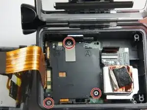
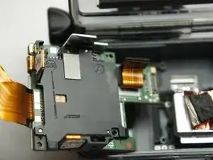
    • Use your fingers and carefully pull out the motherboard from under the lens. It may take a little bit of adjusting to get it out.

Conclusion

To reassemble your device, follow these instructions in reverse order.

Matthew Tinkey

Member since: 27/08/15

892 Reputation

0 comments