Introduction
Glade Automatic Spray Holder SJC-180 could have some loose wires or a burnt circuit on the circuit board. The guide will show you the wire connection areas and circuit boards with problems and how to fix it.
Tools
-
-
Instructions for disassembly can be found with guide Glade Automatic Spray Holder SJC-180 Battery Terminal Replacement
-
-
-
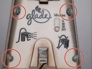
There are 4 screws that need to be removed to expose the inner components (such as the motor). Use a Phillips head screwdriver to remove the screws. Gently pull the screws straight out to avoid disrupting the components you are exposing.
-
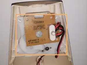
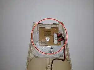
Once the cover is removed, take a picture to reference when you're reassembling the device. The larger electrical board is on the top. The plastic gears are easily moved out of their positions when removing cover and board.
-
-
-
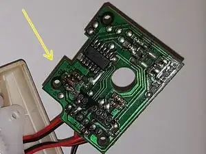
The first circuit board to inspect has the timer switch on it. This circuit board is the larger of the two that are part of the device.
-
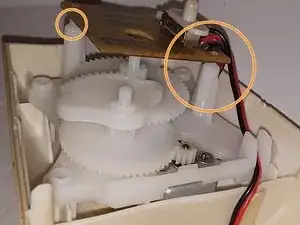
The circuit board is held in place by 3 pegs. The pegs are plastic. This means you do not need special tools to remove the circuit board. It will pop off using your fingers.
-
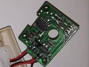
Flip the board over to look for loose wires or any burnt spots. This one is okay.
-
-
-
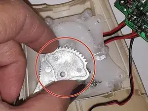
It is best to remove plastic gears before flipping the plastic plate holding everything together. The gears will fall out. Start with the fan shape gear. No tools needed; each gear is held into place by pegs.
-
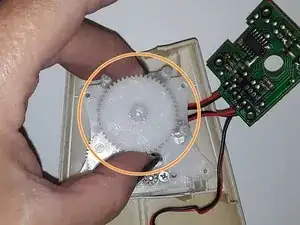
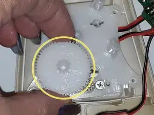
Next is the largest gear. It is centrally located.
-
Last is the medium size gear. Located towards the bottom left.
-
-
-
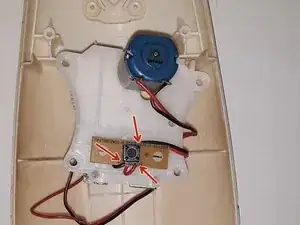
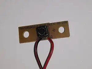
Next locate the small circuit board. Red arrows indicate where the wires are connected to the board.
-
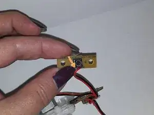
Once pulled off the 2 pegs holding the small circuit board, the red wire came off of the board.
-
-
-
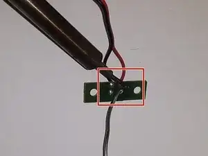
Solder the red wire back to the correct point on the circuit board. You'll be able to see the original factory solder point close to the edge of the board. It will be next to the black wire.
-
Once done with the solder, wait until it has cooled and pull gently to verify that it is securely attached to the circuit board.
-
Finished the circuit board and wire reattachment.
-
To reassemble your device, follow these instructions in reverse order.
