Introduction
It is shown step by step the complete disassembly of the device. Since there was no sign of life any more, I took it apart. The problem was finally a loose plug, which stopped the power supply of the device. The example shown here is unfortunately broken off from the outer shell, but this should not change the procedure.
-
-
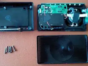
The metal grille, in the front of the device by pry remove. Here is a thin plastic or metal object to use (in the picture is a letter opener to see), a coin is actually too thick. This can be a little hard!
-
There may be a splice on the floor, but in my case it did not resist.
-
-
-
With a PH1 screwdriver, the two remaining screws which hold the two larger boards arranged above each other can be removed.
-
The flat white plugs can be removed with a screwdriver from the board.
-
The width on the left edge of the device is held in place with a brown clip that can be easily pulled out. Thereafter, the flat cable is directly loose.
-
-
-
When removing the board, be sure to watch out for the soldered cables, which will not let you play too much.
-
Below are two black spacers (plastic) to light. Can be removed by hand or with tweezers.
-
-
-
Now the media panel can be removed together with the bottom chip. It is essential to pay attention to the plug contacts between them. (see 2nd picture)
-
Next, the board is located on the charging socket sits. To do this, remove the adhesive pads.
-
-
-
The assembly is actually the same backwards.
-
Clean the area around the controls THOROUGHLY because they are otherwise always "activated".
-


Repeat the steps in order to reassemble your device.
One comment
Very helpfull, tks!!