Introduction
If you memory card is corrupt or not working, this guide will demonstrate how to locate the memory card and replace it with a new one.
-
-
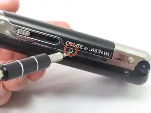
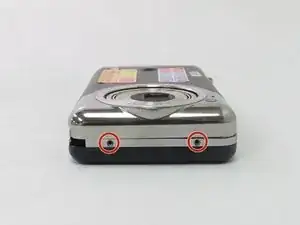
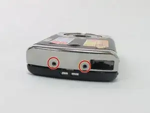
Begin by removing the 5 screws (located: 2 screws on either side and 1 screw on the bottom) using the PH000 head in the Precision Phillips Screwdriver.
-
-
-
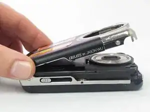
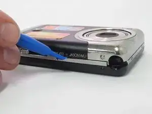
Using your hands or an opening tool, pry off the silver frame, taking special care at the top of the camera where the buttons are as it is a little harder to pry off.
-
-
-
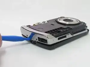
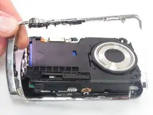
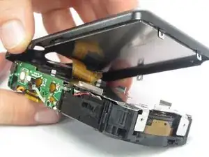
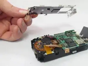
The last part of the casing to disconnect is the back that houses the LCD screen.
-
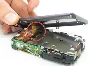
The screen is attached by a connection ribbon. Gently pull the casing and screen away from the camera body to disconnect the casing.
-
-
-
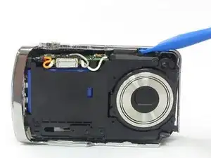
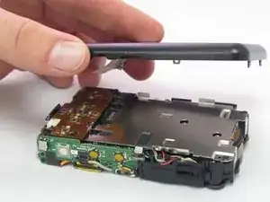
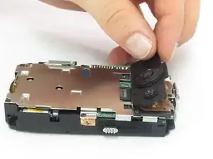
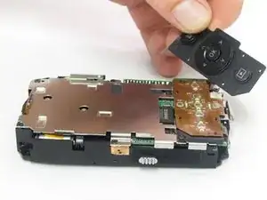
After the casing is removed, use your fingers to carefully lift up on the rubber pad, if it didn't already fall out during step 4.
-
After the pad is removed, the 2 Phillips head screws holding the control board will be exposed.
-
-
-
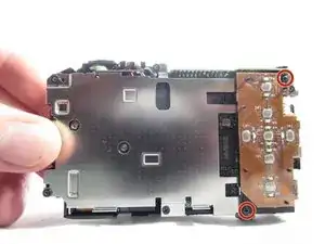
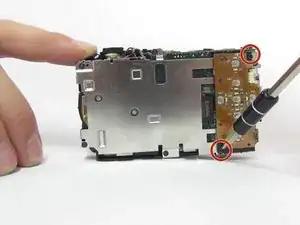
Using the Phillips precision screwdriver with the PH000 Phillips bit, remove the two 1.5mm screws.
-
With a firm grip towards the bottom of the control board, gently pull away from the camera, removing the ribbon from the connector.
-
-
-
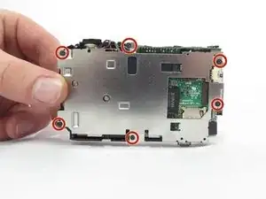
Locate the six 1.5mm Phillips screws that are holding on the interior camera frame.
-
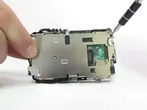
Using the Phillips precision screwdriver and the PH000 Phillips bit, remove the 6 screws.
-
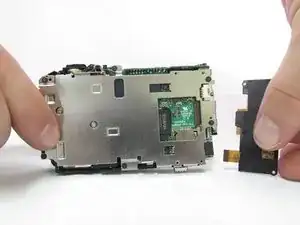
With the screws removed, the interior frame will no longer be fastened to the camera body and can be lifted up and away.
-
-
-
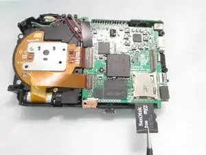
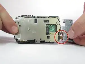
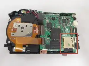
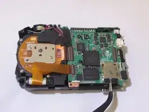
Locate the memory card slot in the bottom right corner of the camera.
-
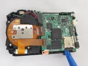
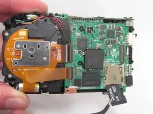
Using a plastic opening tool, gently pry up on the edges of the bottom right corner of the control board.
-
Gently raise the lower right corner of the circuit board by prying upwards with an opening tool.
-
-
-
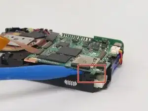
Using a pair of precision tweezers, slide one end under the memory card.
-
Firmly grip the memory card with the tweezers and pull directly outwards.
-
To reassemble your device, follow these instructions in reverse order.