Introduction

The circuit board and its components are delicate, so use caution when disassembeling.

  1. rYETSPNqrokvGLoM
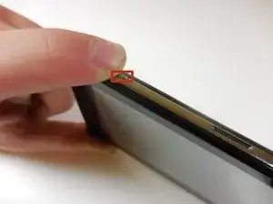
    • Turn the device off by pressing and holding the power button on the top left of the device.

  2. GUvXgbgPOFHaSUUN
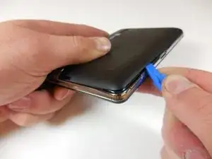
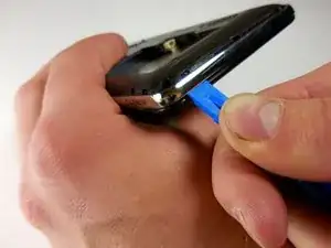
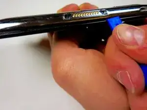
    • Use the plastic opening tool to separate the tabs on the black back cover of the device by leveraging the tool against the frame around the perimeter of the device.

  3. BqjWDE2kGEjd3Qj4
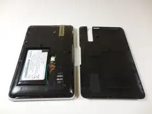
    • Once all of the tabs are popped out, take the back cover off.

    • The back cover is a separate piece from the device.

  4. syfoD1crdbILF4lS
    syfoD1crdbILF4lS
    WhL5bSOT5bEHXOT4
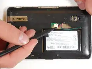
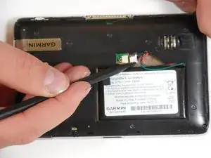
    • Using the plastic spudger, carefully remove the white tab connected to the battery from the device by pulling the tab in the opposite direction from which it is connected.

  5. eMdlKdD1IFYonO3T
    eMdlKdD1IFYonO3T
    OrYvEDIJyUY6gRGn
    ECVNBIxnOAGCVZgZ
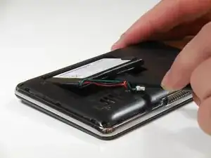
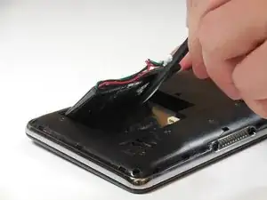
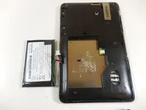
    • Use the plastic spudger to lift the battery up and away from the device.

    • Do not puncture or bend the battery. Serious health complications could occur.

  6. fPdvnrBtKU6bWbgB
    fPdvnrBtKU6bWbgB
    msDXwP3pZhFBdiRC
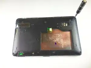
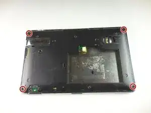
    • Using the T5 bit, unscrew the four 5.7mm screws in the four corners of the device.

  7. SX1RuwjWIuods5Sj
    SX1RuwjWIuods5Sj
    LpNpffNvcJkD3kJS
    ydu2v1hVT1HLuL33
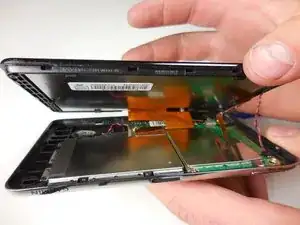
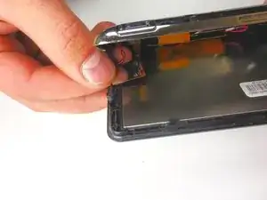
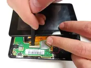
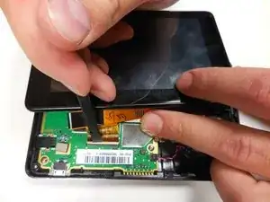
    • Leverage the plastic opening tool to pop the tabs between the black screen and the metal frame around the perimeter of the device.

    • Do not forcibly separate the two pieces after the tabs have been popped as there are connections between the two pieces that could be torn.

  8. sJLRvcFc3xIt6YXT
    sJLRvcFc3xIt6YXT
    MYxPpEIycRJbJTB4
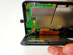
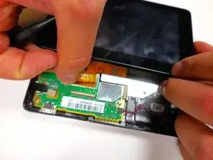
    • Using your fingers, remove the red and black wire from the back of the screen.

  9. Q3BDEPuoVAAua5rB
    Q3BDEPuoVAAua5rB
    d3jTG1hG2TFUOFqb
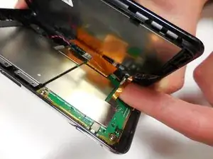
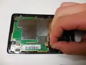
    • Pull up on the smaller orange tab with your finger from the circuit board.

  10. pXSFMEJCyyTVRIlu
    pXSFMEJCyyTVRIlu
    4ApX2mTetQ4ggmdU
    sl51IhCucwZ1dLAo
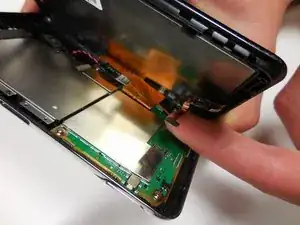
    • For the larger orange connection, there is a white tab holding the connection to the circuit board.

    • Lift this tab gently with the wider tipped tweezers or the plastic spudger and remove the orange connection from the circuit board.

  11. nlstSMZ5STpaFeqd
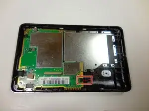
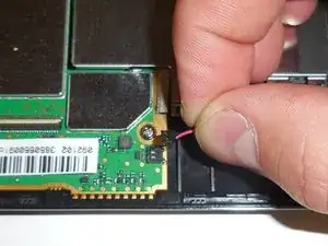
    • Locate the red and black wire connected to the logic board with the round, black, rubber disc that connects to the other half of the device. Gently pull the wire up from the logic board.

  12. TGWthIBQNV3EgOBA
    TGWthIBQNV3EgOBA
    MysYOwBIoQGL3UTE
    WCYXZUSIRHdBtKXc
    • Separate the connection between the speaker and the logic board by gently pulling the wire up.

  13. iJSFJjSkxU6iPBJI
    iJSFJjSkxU6iPBJI
    oDAoAUElngfVQNKX
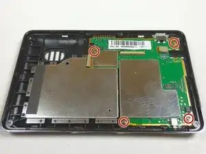
    • Using the J000 bit, unscrew the four 4.0 mm screws from the corners of the logic board.

  14. xmXCLuEGUSWbHFQN
    xmXCLuEGUSWbHFQN
    SGb2GP3MYJrn5BIW
    td4QiVAgKDQ1aLMc
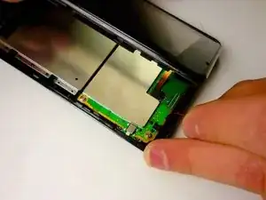
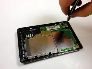
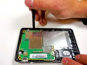
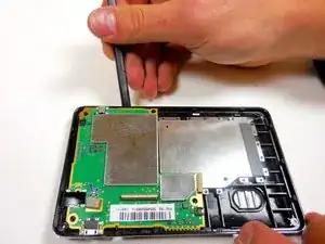
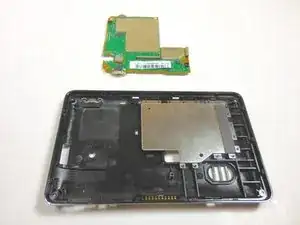
    • Starting near the power button, leverage the spudger to pry up the logic board around the perimeter of the frame.

Conclusion

To reassemble your device, follow these instructions in reverse order.
Kayla Katz

Member since: 11/03/15

576 Reputation

0 comments