Introduction

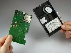
A step-by-step guide to replacing the motherboard in the Garmin Nuvi 680.

  1. XEmeuOsoOXBrouSD
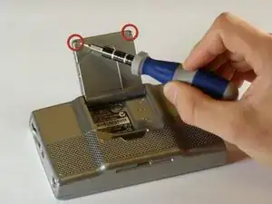
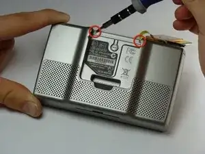
    • Flip open the antenna on the back of the device.

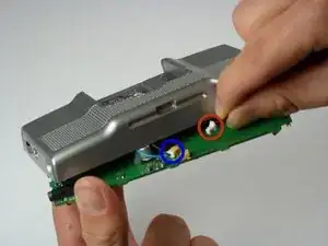
    • Remove the two 4.42 mm screws on the antenna cover using a T5 Torx screwdriver.

  2. LJuoqmXTZBYifRs2
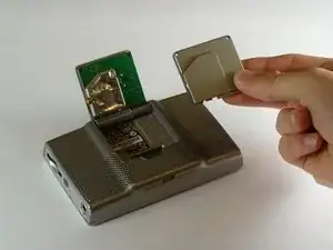
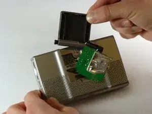
    • Remove the antenna cover.

  3. 4XyqIuEW5qaQbFg4
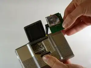
    • The yellow wire is connected to the motherboard, so you cannot disconnect it until you finish opening the device.

    • Pull the antenna circuit board out of its case.

  4. HVmTASQsCPje3hei
    HVmTASQsCPje3hei
    akeCHiyFkeHDt4cE
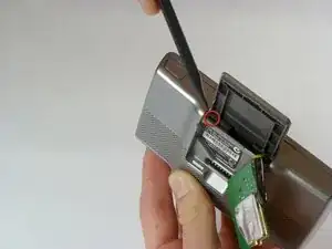
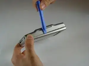
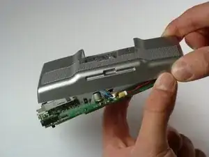
    • Insert the pointed end of a spudger into the leftmost slit of the antenna case.

    • Push the spudger to the right.

    • Slide the antenna case out slowly or you may lose the antenna's spring. The spring is inside the black plastic that holds the antenna case to the device.

    • Slide the antenna case out of the device.

    • Reinstallation tip: first reassemble the antenna casing (place antenna back into its plastic cover), and then re-insert the entire assembly back into the GPS body.

  5. CpDWG2jDZmaVaVLL
    • Remove the two screws on the back of the outer case using a T5 Torx screwdriver.

    • These screws are 10.82 mm long.

  6. GEbIqQrEsKJ1sSOq
    GEbIqQrEsKJ1sSOq
    dZFym3XSrKBmVeKl
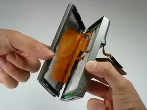
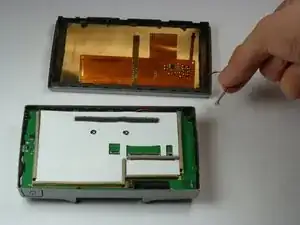
    • Gently pull apart the front and back of the device. The front and back are still connected by ribbon cables.

    • Starting along the top, separate the front and back of the device by pushing an iPod-opening tool into the crack along each side of the case.

  7. QWlBBWPXv3HbTOYR
    QWlBBWPXv3HbTOYR
    tI6oxTARVMVIqMCV
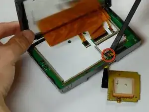
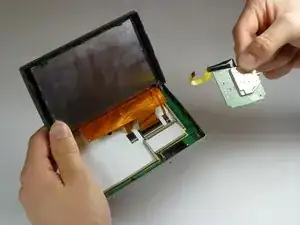
    • Use a spudger to disconnect the yellow antenna wire from the ZIF connector by opening the brown latch holding the wire in place.

    • Remove the antenna.

    The antenna ribbon cable has a latch that must be lifted first. It's a light muddy brown color. It flips up and away in the opposite direction of the ribbon cable.

    ewkpates -

  8. q1wKQy1WogBKUcRC
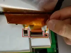
    • Do not remove the ribbon cables without lifting the latch or the cable will be damaged.

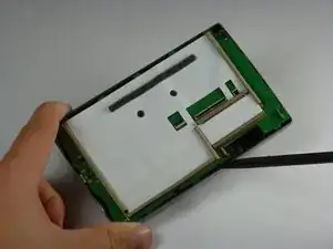
    • Lift the latches on the ribbon cable connectors. All the ribbon cables may have latches. The right most latch may have a latch that flips in the opposite direction from the others.

    • Gently pull the ribbon cables out of their connectors. They should slide out easily.

    • Do not separate the two halves of the device yet or the on/off cable may be severed.

  9. CBVW3CALGtGJNJ4t
    CBVW3CALGtGJNJ4t
    Ij2L5xHDZHZ5tyjy
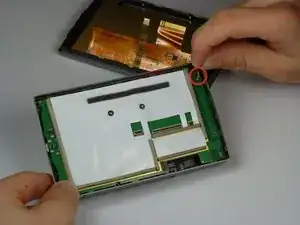
    • Gently pull the cable for the on/off button straight up to remove it.

    • The two halves of the device may now be separated.

  10. OM3pbUfoCAQIHQj4
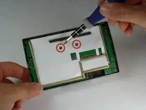
    • Use a PH1 sized Philips screwdriver to remove the two screws shown.

    • These screws are 6.88 mm long

  11. LFu2TImc5YDdep2N
    LFu2TImc5YDdep2N
    RDUqYBLptBiUVfSH
    • Carefully separate the motherboard from the outer case or the speaker and battery cables may be damaged.

    • Use a spudger to lift the edge of the motherboard.

  12. QOPrQNr51LqqSpKm
    • Gently unplug the cable for the battery

    • Gently unplug the cable for the speaker.

  13. CFqaLQw2hKIT1JlS
    • Lift the motherboard out of the outer case.

Conclusion

To reassemble your device, follow these instructions in reverse order.
Chris Marzano

Member since: 21/01/11

968 Reputation

0 comments