Introduction

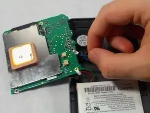
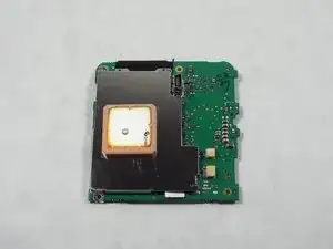
The motherboard on the Garmin Nuvi 200W is a circuit board in the device that operates the whole device. The motherboard occasionally has a component fail, preventing the device from working. Should this happen, the entire Nuvi 200W unit will be inoperable.

This repair is best done in a clean, dust-free environment. The sensitive electronics inside the Nuvi 200W will not respond will to sand and other small particles. It is also important to leave yourself ample time to effectively navigate the motherboard removal process.

  1. RnUuBm2Ub24xwuqv
    RnUuBm2Ub24xwuqv
    l5VeQt2qosCtcVIb
    a1C1DdxBwR3cOqxC
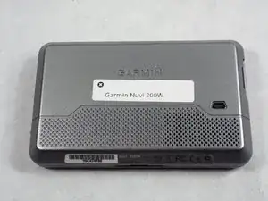
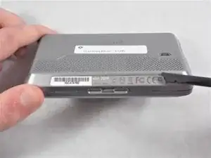
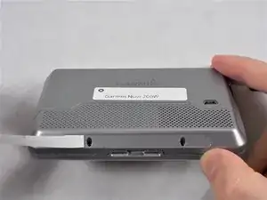
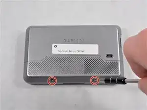
    • Peel off the sticker in order to find the two Torx T5 screws.

  2. DgW14b6LGIIjGoA4
    • Remove the two 4mm T5 Torx screws.

    What size screwdriver do I need?

    Roman Justice -

  3. ULTCN4L2UGkoxIgF
    ULTCN4L2UGkoxIgF
    QfRwyGabBL163oHT
    MrIpuff5kvQPsYPh
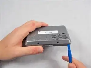
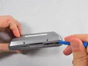
    • Carefully, using your plastic opening tools find the crease which separates the front and rear covers.

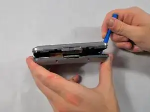
    • Once you have a little gap, work it around the whole device with the tool to get separation.

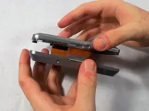
    • There is a ribbon cable between the two covers, be very careful when taking them apart to not damage the ribbon.

    No connecting cable in the picture. Perhaps include a photo or direct the reader to one in a future step.

    Roman Justice -

  4. DOVJSTrNS5V3XXYU
    DOVJSTrNS5V3XXYU
    PGyKL5QQOnPMRGrL
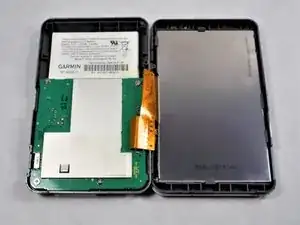
    • After the case front and rear are separated, carefully lay the two sides down without disconnecting or damaging the orange ribbon cable.

  5. YUjDFl6jP6K5FsrV
    YUjDFl6jP6K5FsrV
    g6hIvyQy5rWCEthj
    wL4l1IdwvQ3ODSqj
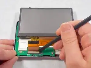
    • Carefully use the black spudger to lift the white retaining clamp on the display cable ZIF connector.

    • Make sure to lift up on the white retaining clamp and not the ZIF connector itself.

    • Slide the orange ribbon cable away from the ZIF connector.

    My 200W had a different connector arrangement. I couldn’t disconnect the display cable which connected into the middle of the motherboard not the edge as shown, nor the other two cables either side, but if I was careful I could get enough clearance to undo the screws holding the motherboard (one of which was under a metal screen which was stuck down but could be peeled back).

    James Warren -

  6. Y6uPxGLMv24DEnlP
    Y6uPxGLMv24DEnlP
    ncgvKMOsF3TygvAx
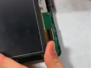
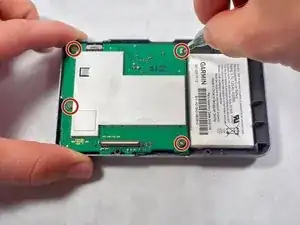
    • Using a screw driver, unscrew the four 2mm screws holding the motherboard in place.

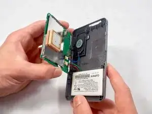
    • Gently lift the motherboard away from the rear cover. Take care to not damage the wires or ports that link the motherboard to other components.

  7. O5sTDG2ciaBICVea
    O5sTDG2ciaBICVea
    uiAgQQWH1OPbbcWb
    4T66IbGKFHgwKMMM
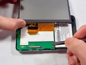
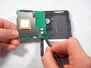
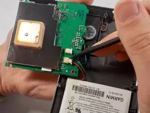
    • Using the black spudger, apply pressure to nudge the plug out of its port.

    • Repeat this process for both ports.

Conclusion

To reassemble your device, follow these instructions in reverse order.
Nick Scharr

Member since: 08/03/17

222 Reputation

0 comments