Introduction
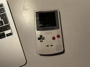
This guide will show you how to build a Game Boy Pocket Color.
The goal is to have a fully functional Game Boy Color inside the shell of a Game Boy Pocket without many visual giveaways other than the color screen and the (optional) infrared port.
Word of caution: When I did this myself for the first time it took me multiple days and i was frustrated a few times, because it is a very difficult and risky feat. (Is that the correct word here?) Also you can’t really test the console until it is about 80% finished, so there’s some anxiety involved too. Do not let these warnings discourage you however, it is really worth the effort, but be aware of the great challenge!
The finished console can be used with a modern IPS screen or the original Game Boy Color screen, although it is smaller than the original Game Boy Pocket screen, so only a few people will go with that option, if any. I will show both methods, however the IPS method will be preferred, because you can drop a big chunk of wiring work, since a lot of the power wires are only required for powering the original screen. The optional steps will be marked in [COLOR].
Wiring up the Infrared port is optional too, the steps that can be skipped will be marked in [COLOR].
The duration of the mod depends on your skill and on how compliant the parts are. Some tiny solder points sometimes took a very long time for me to accept the solder so the wire would finally stick. It can range from a few hours to several days.
Tools
Parts
-
-
You can follow this guide to disassemble the Game Boy Color: Motherboard Replacement Guide
-
You can follow this guide to disassemble the Game Boy Pocket: Motherboard Replacement Guide
-
Game Boy Color Motherboard (as mentioned in the parts list)
-
Game Boy Pocket Motherboard (as mentioned in the parts list)
-
Game Boy Color Infrared Cover
-
Game Boy Pocket Shell (as mentioned in the parts list)
-
Game Boy Pocket Buttons (as mentioned in the parts list)
-
-
-
Get cutting! Mark the Game Boy Color Motherboard slightly below the cartridge connector (in my case it was exactly XXXmm from the top edge) and cut the board.
-
I used a sharp Stanley cutter to score the cut over and over until it was thin enough to start bending. I then cut some more and bent it more until it cracked. Then I cut from the other side until I was through and had the Game Boy Color Motherboard in two pieces.
-
You can also use a Dremel tool to cut the board, but i wanted the cut to be very precise and clean, and I didn't trust myself enough, to not mess it up with the Dremel.
-
-
-
Same thing as before, but for the Game Boy Pocket Motherboard.
-
For the Pocket Motherboard I marked the cut to be exactly XXXmm from the bottom edge.
-
-
-
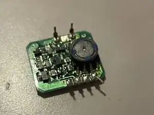
Take the bottom half of the Game Boy Color Motherboard and remove the DC power board.
-
Heat up the old solder and remove as much as possible with the desoldering wick. I've put the wick on the solder joint and held the soldering iron on it until the solder started flowing into the wick. Adding some flux can help too!
-
Repeat on all of the seven pins and if you're lucky, all of the old solder will be gone. But it's more likely that there's still some left and you need to carefully pry up the DC board while trying to heat up as many of the pins at the same time as possible. I used the iFixit Spudger between the DC board and the Mainboard, applying light leverage.
-
Doing so while heating the pins will slowly open up the gap between the two boards more and more, until it eventually comes out all the way.
-
This may take some time and you should not rush it, because you don't wanna break the DC board. They are pretty rare and even though there is a replacement for it if you decide to go with the IPS screen method anyways, you'll wanna save it or even sell it.
-
To reassemble your device, follow these instructions in reverse order.


