Introduction

Hi!

This guide will show you how to install the IPS screen and adapter inside the Gameboy Advance.

  1. FQtv1v6UntVUhZbZ
    FQtv1v6UntVUhZbZ
    evt4WKJq2JU6NORS
    uV53WW1WLpuX3Xcv
    • Remove the back battery cover by pinching down on the tab and pulling outward.

  2. n2BM6E3TNmNQc1vv
    • Remove the six back panel screws using a Y1 screw driver.

  3. YDNPJjBYq4IIvkO4
    • Remove bottom back panel screw with a Phillips #1 screw driver.

  4. YjidaLAxBustDHfg
    • Remove the back panel by pulling away with one hand and the front secured in the other hand.

    • Beware of right and left triggers, the right and left panels, and the power switch falling off as the back panel is removed.

  5. dEkU6llJcUF2igH3
    dEkU6llJcUF2igH3
    PfOcLcSAP6gX2pXX
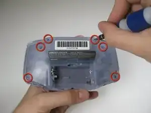
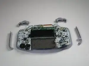
    • Remove left and right triggers by lifting and pulling them away from the system.

    • Do the same for side panels.

    • For finicky or jammed triggers only. Adjust and correct triggers and reassemble. Most jammed triggers are caused by buttons misplaced or jammed in its enclosure.

  6. fCOBrNvTgtKZ3WC2
    fCOBrNvTgtKZ3WC2
    buPCeDKOkuwUWENq
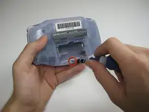
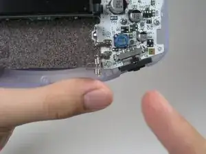
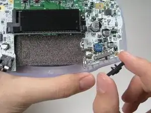
    • Remove the gray On/Off Switch by pulling up and away from the unit. Replace with another switch if necessary.

  7. ODjLTdxT2hd2rIF4
    • Remove the three screws on the circuit board with a Phillips #1 screw driver.

    • The last screw on the right is not included on some Game Boy Advance systems.

    some motherboards only have 2 screws holding it in place. keep this in mind if you cant find one

    Max R. -

  8. fACppBePP3QF5XAR
    fACppBePP3QF5XAR
    Po2GpWoUg3UvggRU
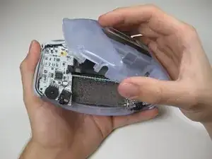
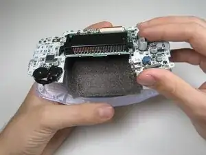
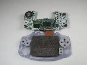
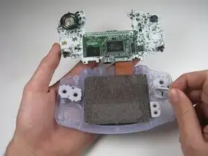
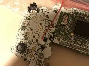
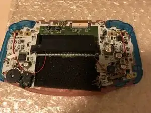
    • Pull circuit board away from the front panel by pulling up at the bottom of the circuit board, keeping the top ribbon still connected.

    • Beware not to damage the top ribbon by pulling up gently.

  9. ZhG4WYWRBXIQS1nl
    ZhG4WYWRBXIQS1nl
    TmsfPpSUY2P22rSV
    ZqTvGZGvqcNWTJxb
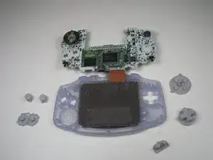
    • Remove the rubber button pads from their pockets.

    • Remove the plastic buttons and the D-pad from beneath the rubber pads with tweezers or by hand.

  10. Y1XGVqih1NjNZbsV
    Y1XGVqih1NjNZbsV
    BqM6MXAjJ3V2XfDh
    ZYQ4E4KRqZy6ME1W
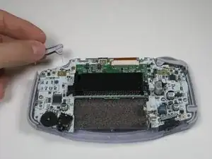
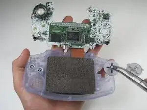
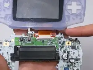
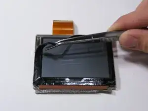
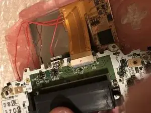
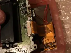
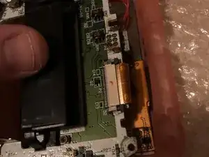
    • Use a spudger/tweezers/fingernail to unlatch the LCD ribbon port by pulling the grey tabs on the sides upwards (towards the top edge of the PCB).

    • Once the LCD ribbon port has been unlatched, the LCD ribbon should very easily slide out and can be removed with zero force using fingers or tweezers.

    Guide does not indicate that the ribbon cable port should be UNLATCHED before attempting to remove the ribbon cable, I strongly suggest revising this as someone unfamiliar with these style of ports may assume that the ribbon cable is a compression fit and just needs to be "pulled" free of the port.

    This is a terrible idea that will potentially result in tearing the ribbon! Please consider revising guide to add a step to indicate the proper method/detail for unlatching the LCD ribbon port! Thanks :)

    Ben Steel -

  11. StGr2Ks6JuTNdsoo
    StGr2Ks6JuTNdsoo
    fJZogxVx2dKyOrVY
    BGKsVlcA1ufbonoB
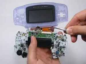
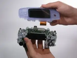
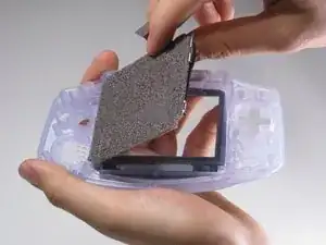
    • Use the spudger to lift the screen from the front panel. Place the spudger in the space directly left of the D-pad.

    • The screen and the front panel is connected by a black tape that could rip if not removed carefully.

    • You can use an iOpener or a hair dryer on the other side of the front panel in order to soften the black tape.

    This is a BAD place to pry on a functioning LCD. I used this exact method, slowly and carefully, and my LCD shattered.

    Instead, remove the lens (it’s worth it to sacrifice the lens adhesive to save your LCD), and gently and slowly press with a gloved thumb on a corner to push it through from the front of the Game Boy. Let the adhesive release itself, don’t force it. If the room is super quiet, you should be able to hear a faint peeling sound, even if you can’t see anything moving. That means you’re doing it right; just wait and it will release.

    trevorsklar -

    Actually you can just pry under the ribbon cable. The LCD has a metal frame there that allowed me to slowly and carefully pry from that point without (re)breaking my LCD.

    trevorsklar -

    Yep. Same thing just happened to me :(

    Robert Carlson -

  12. 6galgqIuLon5Ce6X
    • Use the tweezers to remove the black tape if needed.

  13. HcIUehKuRDcEvKen
    HcIUehKuRDcEvKen
    fDVZT44QsVIWLwf6
    cfUB4ZfUKCQuTcyn
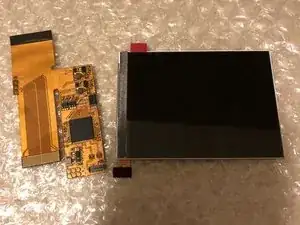
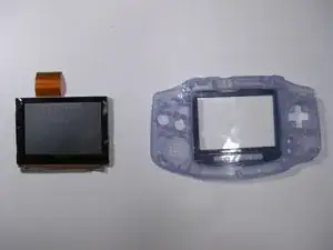
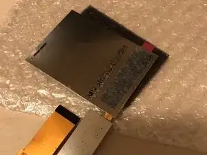
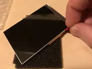
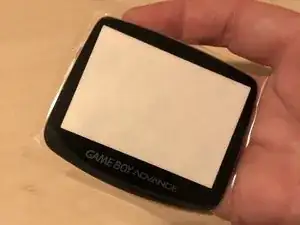
    • First of all, unpack everything and check if it's all good.

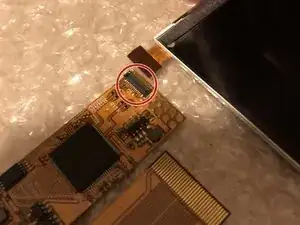
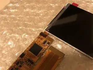
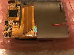
    • The connector where the screen needs to be attached is circled in red. It's the only connector on the adapter.

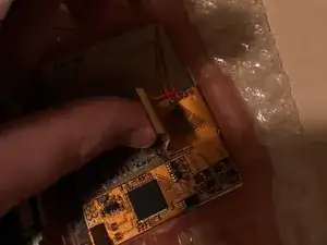
    • Press the LCD cable straight on the connector (be sure that's it aligned correctly, otherwise you could damage the connector!)

  14. Avfo1nRExErtmFT6
    Avfo1nRExErtmFT6
    FpdEK5mknvgY4xIe
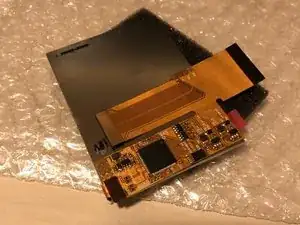
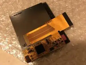
    • Fold the adapter to the backside of the screen and check if everything looks good and falls in place. If it looks like the 1st photo, it should be good to go.

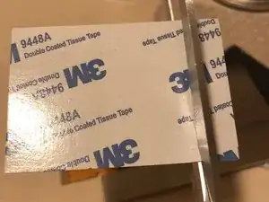
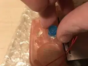
    • Cut some double side tape for the next step.

    “A layer of insulating plastic film on the back of the screen Don't tear it off.”

    This is a warning from the Funny Playing installation guide.

    The kit shown in this guide appears to use a different ribbon/interface from than the one sold by FP. But the LCD looks exactly the same. If you havn’t experienced negative side effects from doing this, I would consider the double sided tape step you mention below a mitigating factor.

    Jon Nielsen -

    Hi Jon!

    Thanks for your comment!

    At this moment it still works fine for all the GBA’s I modded.

    As it won’t have any affect if you leave the plastic foil be at the backside, I’ll remove the step from the guide to prevent any damage which can be done if you remove it.

    Thanks again for thinking with me!

    koppie007 -

  15. RFACMM1IRTSlS36V
    RFACMM1IRTSlS36V
    eJwFo3OFWnxswV6C
    FhXe2TAiwXDt5nF6
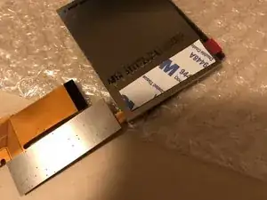
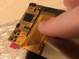
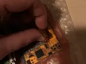
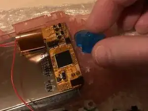
    • Paste the double side tape with one side to the backside of the IPS screen (align it with the adapter)!

    • Remove the paper from the tape

    • And adhere the adapter to the backside of the screen, if it looks like the 3rd photo, it's all good to go.

    • Be sure that the IPS screen is connected with the cable to the adapter! Otherwise it will be difficult to align it correctly.

  16. JfnFvDDmipfwiWjY
    JfnFvDDmipfwiWjY
    1yIjg5TxthpVAk2v
    • This is required for 32 Pin motherboards only. Skip this step if you have a 40 pin motherboard! If you are not sure which motherboard you have, please refer to Google. The 32 pin motherboards start with 1 and the 40 pin motherboards start with 0.

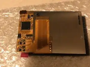
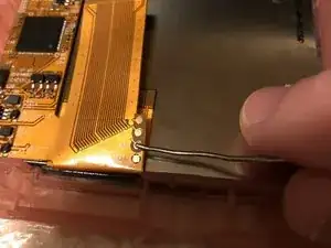
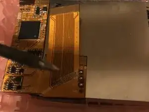
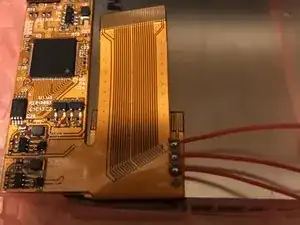
    • Fold the 40 pin cable underneath the adapter as shown in the photos. (only suitable if you have a 32 Pin motherboard!!).

    • For 40 pin motherboard, just leave the cable be, no additional adjustments are required.

  17. ZdoGcTBufjP1pppN
    ZdoGcTBufjP1pppN
    xkWC2eWv1LbAt1lS
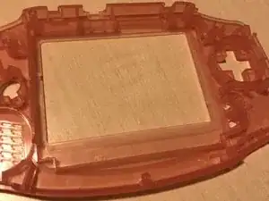
    • You have 2 options. Option 1: buy a pre-trimmed shell. Option 2: Trim the shell by yourself. I have a pre-trimmed shell as it's a very critical step. This guide is meant for pre-trimmed shells only. If you need to trim your own shell, please check on Google what needs to be trimmed and make sure it's trimmed perfectly.

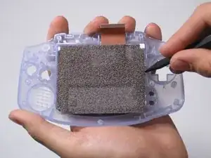
    • Put the double side tape in the shell as shown on photo 2. Make sure it's good at it's place.

  18. AwHgZyYCxWPTJJVE
    AwHgZyYCxWPTJJVE
    roqApHJ4FjJGwJHl
    • You are approaching the point of no return if you follow this step!

    • Remove the foil from the front of the IPS screen.

    • Make sure everything is completely dust free before you continue!

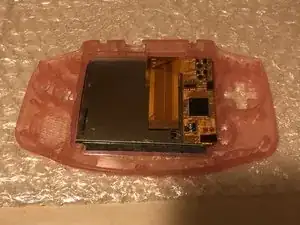
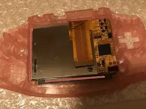
    • Place the IPS screen in the shell. Make sure you place it EXACTLY as shown in photo 2.

    • If your screen is shipped with a blue bracket. Please install the bracket to the LCD before you place it in the shell!

  19. WyQPXjINuUNORCAT
    WyQPXjINuUNORCAT
    OjuY1mRTZIiESJpE
    6njZvQGdTSiIBADf
    • Some of the screens are delivered with a blue bracket, if this is the case. Please skip this step.

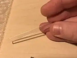
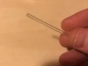
    • Take the 2 plastic clear bars. You have a thin bar and a somewhat thicker bar.

    • Place the thin plastic bar to the left side of the shell. If it won't fit perfectly in, just leave it be. And the thicker bar needs to be placed at the downside in the shell.

  20. WAIcOZgblBLeV1nj
    WAIcOZgblBLeV1nj
    W5rft1hL1YVI1l5W
    NVNhRJQE43uvJQBf
    • Turn the shell and check if the IPS screen sits properly. This is your last change to make sure that the screen is dust free!

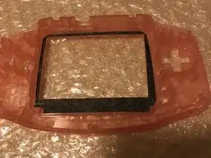
    • Take a new lens and put it in, make sure that everything is dust free before you attach it.

  21. xThORWYHDG6mRjNE
    xThORWYHDG6mRjNE
    HBWLXa1A44CXFNUi
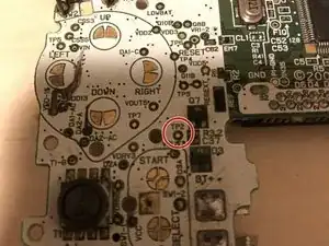
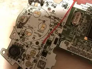
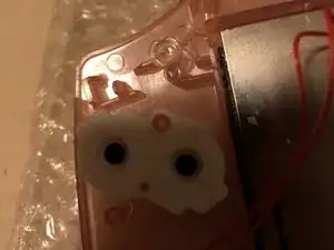
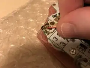
    • Check the ribbon cable. You will see 3 golden round pads with the following text next to it. L, R and SEL.

    • Red circled = the SEL (Select)

    • Blue circled = the R

    • Green circled = the L

  22. eZKyESAkXHNB56B6
    eZKyESAkXHNB56B6
    gOklIEWtNZPEShOl
    WWNWWGL3NLAg1Afy
    • Put some solder on the pads as shown in the 2nd photo.

    • Solder the 3 cables to the pads. I advise to use 3 different cable colours, but if your kit only have red cables, use them.

  23. 2qBlOMvIsNfUcCmr
    2qBlOMvIsNfUcCmr
    jGwTC4KHRtffaNIF
    XIEMUTWWJGO5EdMd
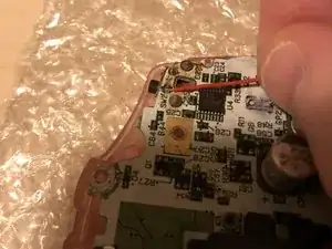
    • Locate the TP2 pad on the motherboard. Put some solder on the pad.

    • Solder the SEL cable to the TP2 pad on the motherboard.

    • For the finishing touch, you can put some tape on it.

  24. VoPKcKVLwkaSF41G
    VoPKcKVLwkaSF41G
    xXIEydSuDkMbk5De
    • If you have a 40 pin motherboard, you can skip this step. Make sure that the 40 pin cable is correctly attached to the motherboard.

    • For 32 pin motherboards, please fold the cable as shown in the pictures.

  25. 4DOVPIPBPaqrJCZQ
    4DOVPIPBPaqrJCZQ
    yZEp3PYICOQjNJI3
    JXlM6ylC3Btx6yYi
    • Put the cable in as showed.

    • You should be able to bend the cable a bit if required.

    • This is shown for 32 pin motherboards but the 40 pin cable should fit as easily as this one.

  26. mXWx51VkdNwSfNYW
    mXWx51VkdNwSfNYW
    1ixFURQ2jwftZkow
    ERJpYufoI35MNNkg
    • Before you put the motherboard in, don't forget to put in the buttons first!

    • And don't forget the plastic LED cover and rubbers.

  27. Vw3xUYDRMBkqCTml
    Vw3xUYDRMBkqCTml
    MfCEeGmvh3GlaTsK
    vnG2FglQbAvqbYoA
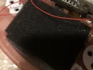
    • If you got some black foam in the kit. Just place it in now, before you attach the motherboard. This is not necessary, but will protect the motherboard and the cables soldered to the adapter.

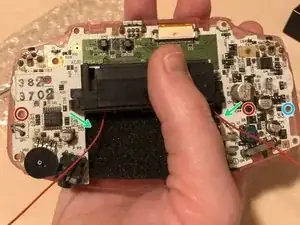
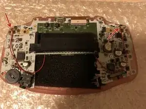
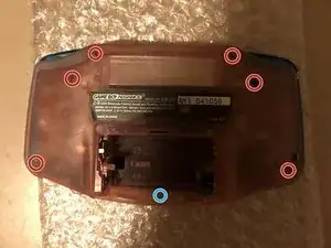
    • Attach the 2 screws circled in red. Be aware.

    • The 2 green arrow shows how you can route the L and R cables. The L cable needs to go the RIGHT side and the R cable needs to go to the LEFT side of the gameboy in this case. (This is because we have flipped the gameboy as shown in the picture, it's mirrored)!!

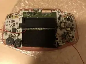
    • The last pictures shows when it's all good and when you are ready to follow the next step.

    • Do not forget to install the cable to the motherboard and to lock the connector.

    • Some models have a third screw circled in blue.

  28. EaU4LxBovWGrqHhM
    EaU4LxBovWGrqHhM
    mvS21FcSY4mcWrUL
    shu4v43cNWclQSiL
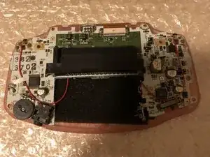
    • Solder the R cable to the left side. Please check the first picture to which solder pad it needs to be soldered on.

    • Solder the L cable to the Right side. Please check the second picture to which solder pad it needs to be soldered on.

    • Check the red arrows to confirm if it's all good. If it looks like the last photo, you are good to go.

  29. OWUHljfY1nXTMB2h
    OWUHljfY1nXTMB2h
    leoc3NSIrxnI6pTo
    RADrlHvNEPrUrFgo
    • If the cables won't seat where you want them to be, just use some tape again.

    • Now put on the other buttons!

    • Put in the screws back again, circled in red. Please be aware, the blue circled screw is smaller than all the other screws.

  30. TPhi5aVpolPBlnHk
    TPhi5aVpolPBlnHk
    uTgdGlqnKwqZutqT
    P6pCahcoj3FY1POp
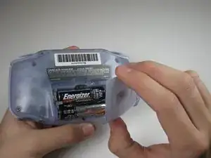
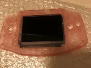
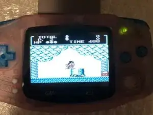
    • Put in some batteries and test the gameboy. When it looks like the 1st picture, it's a success!

    • Hold the SELECT button and press the L button to decrease the brightness. Hold the SELECT button and press the R button to increase the brightness.

    • You can click multiple times to increase and decrease the brightness.

    • Put in a game and test if it works. If it's working fine, congratulations with your IPS screen!

Conclusion

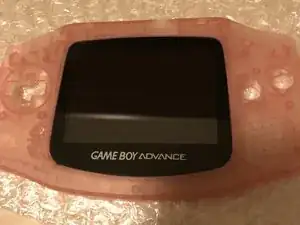
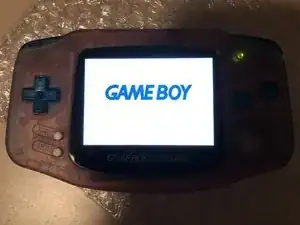
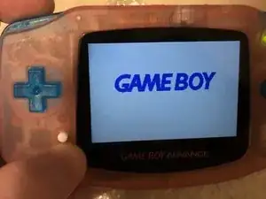
And that’s all! If everything went well, you should have a blacklight screen installed in your GBA.

koppie007

Member since: 22/08/13

10603 Reputation

7 comments

Since you did both. Which do you prefer the ips or the ags 101?

jp1357 -

Hi! I prefer the IPS. This because it’s easier to fit (in a pre-cut case) and your batteries will last longer. You can also increase and decrease the brightness of the backlight.

koppie007 -

Hi I already have a gba with the ips backlight installed already and I'm looking to replace the buttons, shell, and, screen lens. Will I need to solder anything or do I just replace it?

Demitrius Graham -

Hi! No, you can take out the motherboard with the adapter, BUT be sure you unplug the screen from the adapter first. When you did this, transfer the screen first. When the screen sits flush, connect it to the adapter and build it back in :). Good luck!

koppie007 -

did every step but when i turn on my gameboy i get a blackscreen with backlight but no video. i think my ips display is broken.

Parvis Parvis -

Hi!

I regonize this issue as this did happened to me too (doing a lot of IPS Mods and had this issue 2 times of all the GBA’s I modded). It’s not the IPS screen, it’s the adapter which is broken. When you replace the adapter for a new one, it will work with your installed IPS screen.

koppie007 -

Hi - I have this Mod ALMOST working. My problem: when I hit "Select" it acts as though I'm holding "Select + L Shoulder" (it dims) and the L Shoulder button itself doesn't seem to work at all. Any tips on what I did wrong? The R Shoulder works and select + R brightens as it should.

James Dziezynski -