Introduction

If the touchscreen display of your GE Carescape R860 is powered on but unresponsive to touch, use this guide to replace the Touch Bezel Assembly.

Before using this guide, ensure that the screen lock is not turned on. Most commonly, a frozen touchscreen is the result of an accidentally switched on screen lock.

For additional information regarding this replacement, see section 9.5.5 (pg. 253) of the GE CARESCAPE R860 Technical Reference Manual.

  1. e1L62IfRIYJxRNWR
    • Using an opening tool, gently pry the alarm light lens (boxed) from the display unit.

  2. NPPHCes4s62KitHY
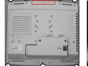
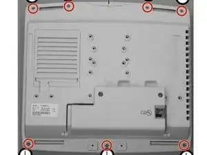
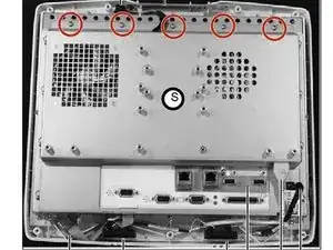
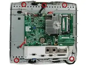
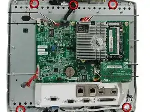
    • Loosen the seven screws that hold the rear housing using a Phillips #0 screwdriver.

    • Remove the rear housing.

  3. envnMAty52AbNoII
    • Cut the cable tie holding the two cables at the lower right side using scissors.

  4. p5HmKrBPheLvMpLM
    • Disconnect the touch controller cable.

  5. FAPu6ZUNuSeCB1rT
    • Disconnect the Keypad harness at the Carrier Board.

  6. FsYuIBoB5ZIaaHu4
    • Disconnect the encoder harness from the Carrier Board.

  7. ZvT3CgjjqhPFtEZe
    • Disconnect the speaker harness from the Carrier Board and set the speakers aside.

  8. T3CJiLZYHR6YdTaG
    • Disconnect the alarm light harness from the Carrier Board.

  9. fyOkJuiZKCbSkJTG
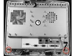
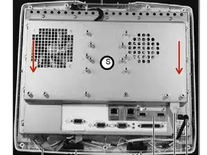
    • Loosen (do not remove) the five screws at the top edge of the shield just enough to raise it and slide the shield away with a Phillips #0 screwdriver.

  10. uGjtFOVxJCv5M5jm
    • Loosen the four screws along each side of the shield with a Phillips #0 screwdriver.

  11. bKxWrJDytjikh5VT
    • Remove the four screws at the bottom edge of the shield with a Phillips #0 screwdriver.

  12. xyeMBELZTDrx2xal
    • Slide the shield down to disengage the touch controller harness connector.

  13. tEycgQ1wR34nOKdc
    • Remove rear housing and shield (refer to “Display Unit Disassembly”).

  14. RAw3beJfWUtUEnCR
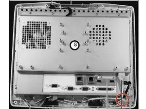
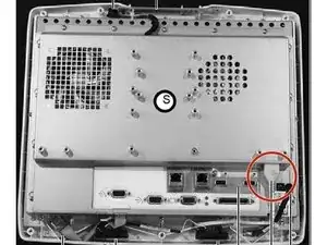
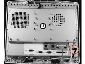
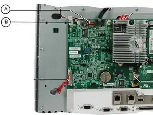
    • Disconnect the Blower fan cable (A); remove the p-clip (B) holding the harness to the Carrier board.

  15. bYbnKYAS3SgRttBa
    • Disconnect the Carrier board to LCD LVDS harness (22) - two connectors.

  16. JOCftQkmHZpSbQ4f
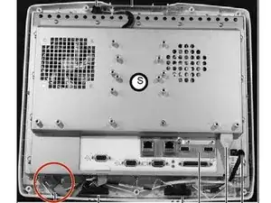
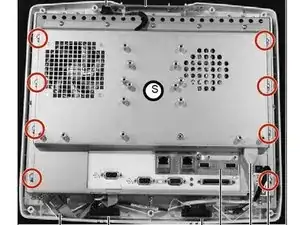
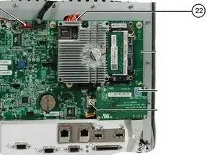
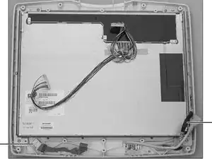
    • Remove five LCD shield mounting screws (circled). Do not loosen any screws that are dabbed with sealing compound.

  17. Yn2tCXVfpQOOcSis
    Yn2tCXVfpQOOcSis
    PChIG5LiixX2jrqn
    • Remove the LCD shield and Carrier board assembly from the LCD Touch Bezel assembly.

  18. gDWJhX4OCYMLtGQS
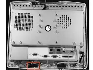
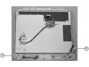
    • Transfer the Carrier Board to Keypad harness (23) and the Encoder assembly (15) to the new LCD Touch Bezel assembly.

Conclusion

To reassemble your device, follow these instructions in reverse order.

Seth Deming

Member since: 10/04/20

133 Reputation

0 comments