Introduction
-
-
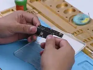
First of all, run a cosmetic inspection of the motherboard. The motherboard is not deformed or water damaged.
-
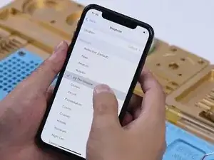
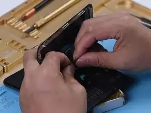
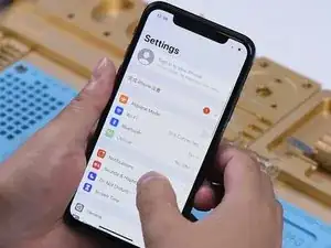
Then we install the motherboard on the phone to test. The phone turns on normally. Go to Settings > Sounds & Haptics. Turn the volume up. Play the ringtones. There is noise in the sound.
-
-
-
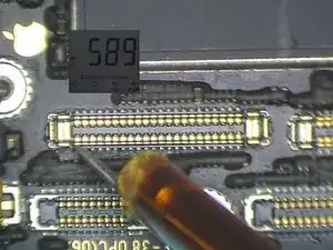
Measure circuits that are related to the speaker on the charging port connector. Turn the phone off. Detach the motherboard. Run diode mode measurement of the pin 1, pin 3, pin 5, and pin 45 on the J6400. The diode values are normal.
-
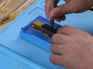
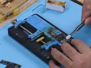
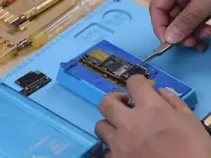
Then we need to separate the motherboard for further testing. Cut through the shielding paper with a Sculpture Knife. Heat the motherboard on the Heating Platform at 165℃. When the temperature has risen to 165℃, remove the logic board and signal board.
-
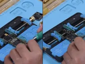
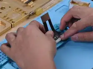
Attach the signal board to the holder. Smear rosin with Soldering Iron at 365℃ and solder wick to remove tin on the bonding pad. Remove tin on the bonding pad of the logic board with the same method.
-
-
-
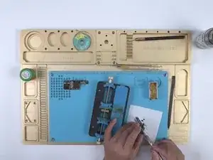
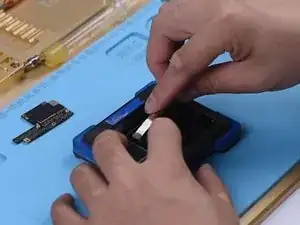
Remove thermal grease with a Sculpture Knife. Clean the motherboard with PCB Cleaner. Attach the signal board and logic board to the Testing Fixture.
-
-
-
Connect the Test Extension Cable. Close the Testing Fixture. Connect the charging port flex cable. Then connect the battery and the display. Short to the ground of the J4300 pin 9 to trigger the boot-up. The phone turns on normally.
-
-
-
Go to Settings > Sounds & Haptics. The ringtones play normally. It can be judged that the noise is caused by pseudo soldering of the motherboard middle layer.
-
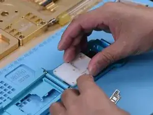
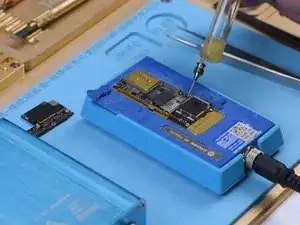
All we need to do next is to recombine the logic board with the signal board. First of all, we need to reball the signal ball. Attach the signal board to the Reballing Platform. Put the Reballing Stencil in position. Apply a layer of low-temperature Solder Paste evenly. Remove the Reballing Stencil.
-
-
-
Put the signal board on the Heating Platform. Heat the signal board on the Heating Platform at 165℃. After the solder balls are formed, turn the power off and cool the motherboard for 5 minutes. Apply some Paste Flux.
-
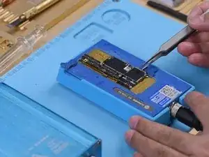
Align the logic board with the signal board. Keep heating the motherboard on the 165℃ Heating Platform. When the temperature reaches 165℃, keep heating for 1 minute. This step is to ensure that the logic board and the signal board fit closely. Turn the power off and cool the motherboard for 5 minutes. Then remove the motherboard.
-
-
-
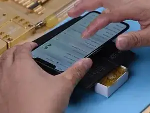
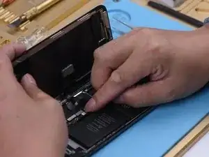
Put the motherboard on the phone. Connect the display and battery. The phone turns on normally. Test the sound. The sound gets back to normal and has no noise.
-
The sound of the iPhone X was distorted. When measuring circuits that were related to the speaker on the charging port connector by pressing the motherboard with multimeter probes, the diode values were normal and we couldn’t find the fault. But the sound remained normal after we separated the motherboard and tested the motherboard with the holding fixture. Therefore, we could conclude that the noise was caused by pseudo soldering of the motherboard middle layer. The fault was cleared after we recombined the logic board with the signal board.