Introduction
-
-
The phone is unable to boot up.
-
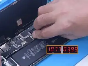
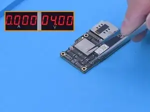
Lift the screen. Disconnect the battery. Connect the motherboard with a power cable. The ammeter shows a current of 1 A. The phone has large current while the boot-up hasn’t been triggered. Therefore, it can be judged that the fault is on the main power supply circuit and related components
-
-
-
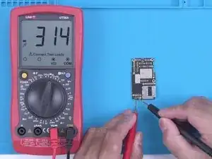
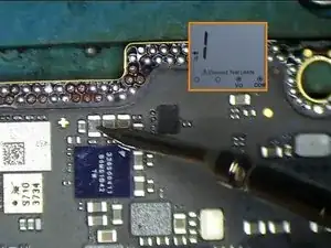
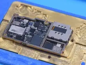
Next, remove the motherboard. Measure the diode value of the battery connector with the multimeter. The diode value is 314, which is normal.
-
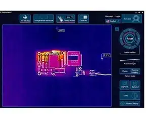
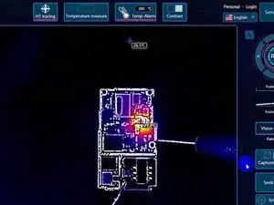
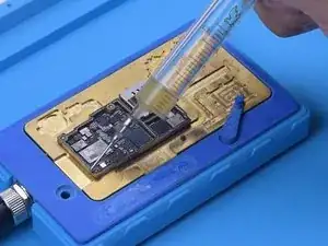
Then we put the motherboard on the thermal imager. Connect the motherboard with a power cable. Areas around the NAND are getting hot seriously. Since NAND is not on the main power supply circuit, we need to separate the motherboard for further testing.
-
-
-
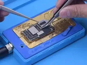
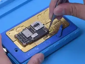
Remove the logic board with Heating Platform at 170 °C.
-
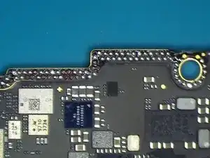
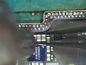
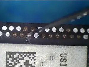
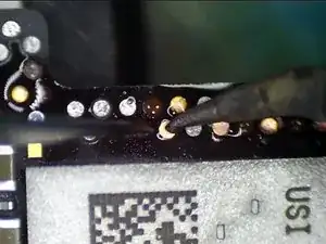
Because the phone has been heavily dropped before, we can see that there are many missing pads on the bonding pads.
-
-
-
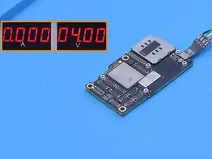
Next, connect the logic board with a power cable. The logic board doesn’t have large current. The fault is probably on the signal board.
-
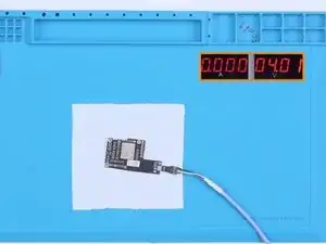
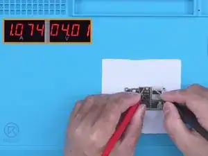
Power up the signal board separately with the probes of the multimeter. Large current appears on the signal board. It can be confirmed now that the fault is on the signal board.
-
-
-
To precisely detect the fault, put the signal board on the thermal imager and supply power to it. It can be seen that the temperature of areas around U5000 reaches 80 °C quickly.
-
Measure the capacitors around U5000 with the multimeter and there is a short circuit. Additionally, a capacitor was found to be burnt out during measurement.
-
-
-
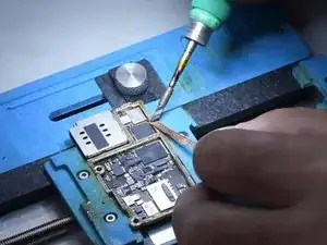
Next, we remove the capacitor. Apply some Paste Flux to the capacitor.
-
Remove the capacitor with Hot Air Gun at 380 °C. Then replace it with a new one.
-
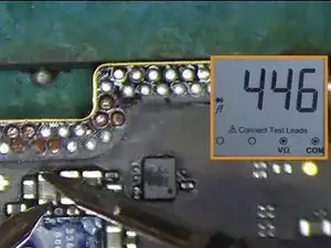
Measure with the multimeter again. The diode value returns to a normal value of 446.
-
-
-
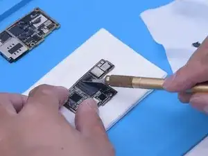
Because there are still missing pads, then we repair those missing pads. Clean tin on the bonding pads of the signal board with Soldering Iron and Solder Wick. Clean tin on the bonding pads of the logic board with the same method, and then remove the thermal paste. Keep cleaning the bonding pads with PCB Cleaner.
-
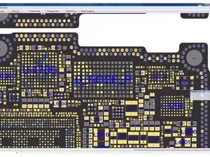
Open REFOX Bitmap to determine the missing pads for repair.
-
-
-
Since some missing pads are grounded, there is no need to repair them . Scrape to show circuits of other missing pads with a Sculpture Knife.
-
Apply tin to the bonding pads with a Soldering Iron. Put the Soldering Lugs in position. Solder with a Soldering Iron at 380 °C.
-
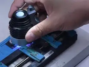
Apply some Solder Mask to the bonding pads that have been repaired. Then solidify with a UV Lamp for 5 minutes.
-
-
-
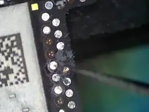
After solidifying, remove excess solder mask with a Sculpture Knife to show the pads.
-
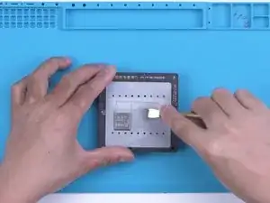
Next, we reball the signal board. Apply a layer of low-temperature Solder Paste evenly.
-
Put the signal board on the 170 °C Heating Platform to heat.
-
-
-
After the solder balls are formed and the motherboard cools, apply some Paste Flux to the bonding pads.
-
Align the logic board.
-
-
-
After recombination and the motherboard cools, connect the motherboard with a Power Cable. The motherboard no longer has a large current.
-
Then trigger the boot-up with Tweezers. The boot current has returned to normal.
-
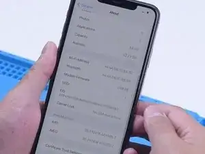
Install the motherboard. The phone turns on normally. The baseband is also normal.
-

To reassemble your device, follow these instructions in reverse order.