Introduction

Use this guide to replace just the RF Cable on your Fairphone.

  1. mTAxpwLBXBobuY5n
    mTAxpwLBXBobuY5n
    QdfIDMURfi6Vccwb
    bXLQZrIlnEjJ24kZ
    • There is a small indentation in the side of the phone near the bottom of the back cover.

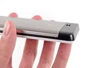
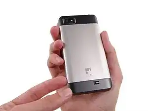
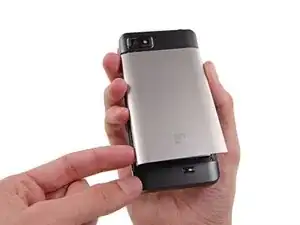
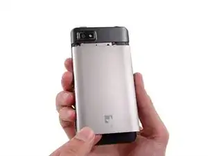
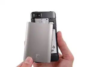
    • With the indentation as leverage, use your fingernail to pry the bottom portion of the back cover from the phone.

  2. RFaJW4GP1UTAdrGJ
    RFaJW4GP1UTAdrGJ
    MGQNn26fTTEkkmVQ
    2DjUSG2snjJ5A6N3
    • Slide the back cover down and remove it from the phone.

  3. d42tJ4wbOSJOXyh1
    d42tJ4wbOSJOXyh1
    Ph5bQmTyD4QCxYYx
    yDi6q24gEXsBA33e
    • There is a small indentation in the back of the phone just below the battery.

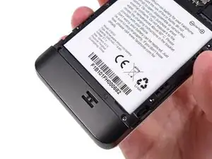
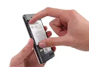
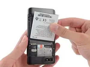
    • Use a fingernail in this indentation to push the battery toward the top of the phone

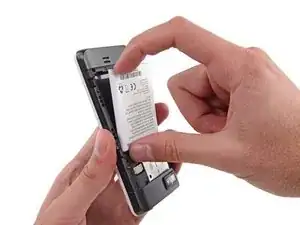
    • Pull the battery out away from the phone.

  4. gsvSJIH1oQuEkJcf
    • Remove the battery from your Fairphone.

  5. TvVTnCTDJyAOmj1Q
    TvVTnCTDJyAOmj1Q
    paHqfqUaXf1qpfXT
    MHq1kfUmppsVq5mw
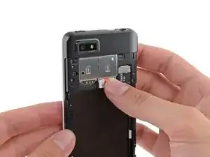
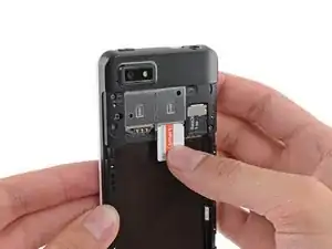
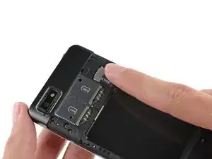
    • Use your finger to slide the SIM card straight down out of its tray.

    • Remove the SIM card from your Fairphone.

    • Repeat this procedure if you have a second SIM card.

    • Be sure to remove all SIM cards before servicing your phone.

  6. pwda1yqpKyUAcaPe
    pwda1yqpKyUAcaPe
    WrMnBCKmphyDPbVp
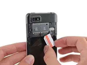
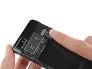
    • If you have a microSD card, use your finger to slide it straight out of its slot.

    • Remove the microSD card from your phone.

  7. MXI4cSWRnfkli2ij
    • Remove the five 3.9 mm Phillips #000 screws securing the midframe to the display assembly.

    The three upper -next to the SIM blocks- screws are a bit longer that the three others. It is important to keep them like this because if not, they will not tight to the whole.

    Jaime Bosque Torrecilla -

    There are only 5 screws. I see none longer than others.

    Viktor Steiner -

    You're right, I've just done it and it's true. Thanks!

    Aiala -

  8. SfKvwtCMthj3SZau
    SfKvwtCMthj3SZau
    PYBEnY1BVnhjVTjH
    uq3jAbPRdjTMYKEB
    • The midframe is secured to the display assembly by several small plastic clips.

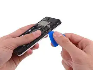
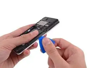
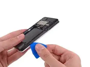
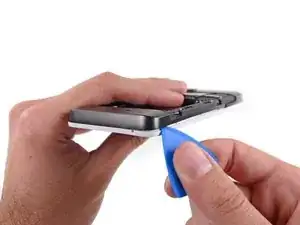
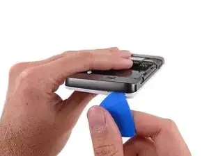
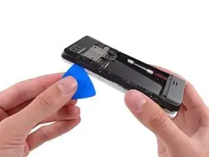
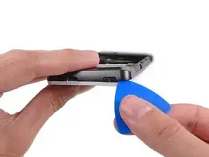
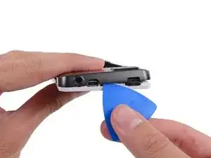
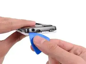
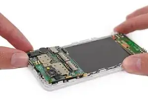
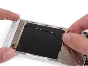
    • Use an opening pick to carefully pry the midframe away from the display assembly.

    • Start just below the volume rocker and work your way down toward the bottom of the phone, freeing the plastic clips along the side.

    No need to be TOO careful. Just remove the whole thing, no stress.

    clem -

    Some stupid person put a sticker on the fifth screw. If you can not find the fifth screw, check if there are any BLACK (yes, black) stickers on top of them. Also, which 'designer' made the first design choice for plastic clips? I WILL FIND YOU. AND KILL YOU. *!&*^#% stupidest way to affirm or secure something!

    maggelo -

    It must be done very carefully: I'd broken both white pieces. Hope has no consequences ...

    Aiala -

    You also can start from the interior (white pieces all around batterie place)

    remy.carl.fr -

  9. ZC5FAkIRnhHSs5aj
    ZC5FAkIRnhHSs5aj
    IumJCLtXZOPQoFWX
    • Carefully round the corner, separating the midframe from the display assembly.

  10. kSWQd6TRSPCIYSKb
    • After rounding the next corner, the midframe should be free along the bottom and the sides.

  11. iQkNQ3HpLP6bLiOM
    iQkNQ3HpLP6bLiOM
    RaHnhIAUHnDmxDYa
    KoXhpQOMed4TogZA
    • Run the opening pick and pry along the top seam.

    • To avoid bending or damaging the opening picks, do not pry near to the power switch, USB port, or headphone jack.

  12. ZC1c2AGOq2ZLF2Nx
    • Separate any remaining clips and remove the midframe from the phone.

  13. qlq2V4mJsiAyWGh1
    qlq2V4mJsiAyWGh1
    bOVLkVxYbvTZU34N
    GOlFZLPjbdAQ4XAK
    • Use tweezers to remove the volume rocker and power buttons from the display assembly.

    • During reassembly make sure the orientation of the buttons is correct. The rubber backings must fit into the channels in the assembly.

  14. FAyRTFiHGYlshYvL
    • Use the flat end of a spudger to disconnect the antenna cable connector.

    • Make sure to only disconnect the connector from its socket, and not the entire socket from the board.

    If you´re replacing the screen you don´t need to disconnect the antenna cable. You can take apart the motherboard, the doughterboard and tha cable together.

    Pacarlas -

    Well, I actually broke the socket. Does anyone know if it can be fixed?

    thanks

    Yoel Schouten Moral -

    I broke it too, what to do now?

    jakob -

    What is the thing left of the camera, below the CC \n TC logo printed on the board?

    Luther Blisset -

    Yep, no need to remove the antenna connectors if you're replacing the display.

    Smorgasbord -

  15. rPQKPSWoDWsirkWw
    rPQKPSWoDWsirkWw
    GZBVcSqiNLWLeyU3
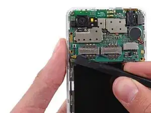
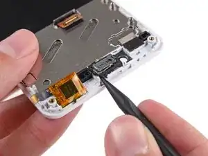
    • Use tweezers to remove the adhesive foam tape from the top of the digitizer cable ZIF socket.

    no adhesive foam on my fairphone

    Sebastian Chica -

    Thank you so much for this amazing tutorial! it works and looks great again!!!

    Sebastian Chica -

    foam tape is black on mine

    Ron Ottervanger -

  16. ENdjutVRKPWo5K35
    ENdjutVRKPWo5K35
    PKDFsWxEugY6iCON
    2gVJTCjTJXMlkq1N
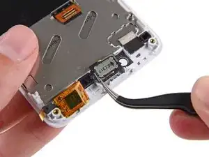
    • Use the tip of a spudger to flip open the tab on the digitizer ZIF connector.

    • Use tweezers to pull the digitizer cable away from its socket on the motherboard.

  17. 2v3hyH6aKNcZpdLn
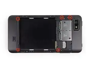
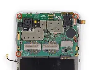
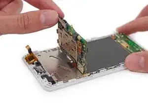
    • Remove the three 2.5 mm Phillips #000 screws securing the motherboard to the display assembly.

  18. XC1DD4YUNVnATFtS
    XC1DD4YUNVnATFtS
    nZ2SU5ruAMppk5ch
    • Do not try to remove the motherboard just yet, as it is still connected to the display assembly by the display data cable.

    • Gently lift the top end of the motherboard up to expose the display data cable.

    • The rear-facing camera may be adhered to the display assembly. Try to pry it and the motherboard up together.

    I had to use a spudger to take off the camera. Not an easy job since it was glued quite well.

    Jan Boonen -

    "mild" adhesive?? Camera is glued pretty well!

    AJ Molenaar -

    First: English isn't my mothertongue, so please excuse mistakes.

    I also lost the camera. But it wasn't a problem. At the end of step 28 it was quiet easier to pry the camera without being careful about the motherboard. Only the reverse was done at step 18 again. I put the camera inside the hole and closed the connector for the data. After that I connected the motherboard again with the display and put all together back. So everything was at its right place.

    At the End everything was perfect. I'm as pleased as punch!

    Ulrike Jasmin Schad -

    This was probably the toughest part. It took it's time to remove the camera from the old assembly. As mentioned in earlier comments, it was glued rather well. Be really careful since there is a data cable connecting the camera to the motherboard, and you won't be able to see it that easily.

    Smorgasbord -

    I took off the camera with the tweezers and thus I had no problem to remove it.

    Werner Lauckner -

    Possible camera fix after damage while extracting: I too had a well stuck camera, and I damaged the camera while separating it from its small metal plate. The tape holding the plate to the chassis was less strong than the tape affixing the camera to the small plate. The camera seems to consist of a sensor (housed in the silver cube), and its lens (the black plastic bit that separated itself from the cube). The lens is still attached to the sensor by four springy bits of wire which I'm guessing control a magnet which causes the lens to move a bit for focusing. I'm guessing that one of those wires have been damaged and therefor the lens is hanging in its most relaxed state. If you poke the lens carefully with the tip of the spudger you will see that it is kind of swimming in there.

    Daniel -

    The effect of this is that the lens is stuck in macro mode. Things that are very close will be in focus. A workaround to get the lens to have a fixed focus on around 1 meter to infinity, is to get the lens to push back as deep in the direction of the sensor as possible. This could be accomplished with crazy glue, or similar. I found a rubber washer small enough to not block the lens, which forces it back when the midframe is reattached.

    Daniel -

    You can actually fix the focus more towards infinity by screwing the inner lens part clockwise.

    Samuli Kaipiainen -

    Lifting the motherboard without breaking the camera module is the most critical step.

    I used tweezers to loosen the camera module from the display assembly.

    It worked best for me to lift the motherboard slightly (!), so I could see the base of the camera module, and then carefully separate the camera from the metal part that it is glued to.

    Have a good lock at the pictures, so you know where the camera module ends and you don't end up breaking the camera module into pieces, instead of taking it off the base.

    I had to push the camera module connector back in again, as it came loose slightly.

    Everything worked out fine in the end.

    Dino -

  19. CWZ1CASDJf2aIhDJ
    CWZ1CASDJf2aIhDJ
    nvK2oJmbixg6NFmU
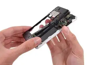
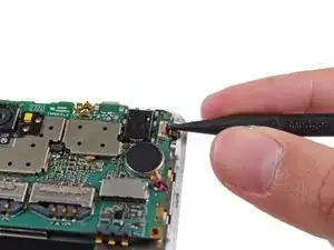
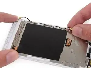
    • Use the tip of a spudger to disconnect the display data cable from the back of the motherboard.

    In this step I found the rear camera unit glued to the display part. It was easy to take it apart and connect it again to the motherboard but at te first moment I was scared.

    Pacarlas -

    Yeah, please make sure you don't remove the socket, cause I did it, and after that it's a pain in the !@# to put back. If unfortunatly it happens, remember that the two points on each side of the sockets should be align vertically (from the phone point of view) and the line to the side closer to the phone side.

    clem -

    In my case the camera also stayed glued to the display part. In fact that was no problem - just leave it connected to its metal pad and take both off together (in my case the metal pad was only midly adhesive to the display part). When reassembling just take off the metal pad from the new display and put in place the old metal pad with the camera on.

    eml -

    It was a good hint to take out the camera and the metal pad together. It worked perfectly well and in the end it was much easier to separate the camera from the old metal pad and to glue the camera on the new pad.

    Mrs Adams -

    when re-connecting the (new) screen to the motherboard, you have to watch out to carefully re-connect the display datacable. the two parts fit neetly together and is has to do a little "click"-feeling when the connection was succesful.

    ksend -

    I reconnected the screen to the motherboard by cutting a small rectangle of cardboard and slide it under the display connector to lift it a little bit. Then you can lay down the mainboard connector on top of it and press it down. It will click in place. Next, slightly lift the topside of the mainboard to remove the cardboard with a pair of tweezers.

    jeroen.hilgers -

  20. QRjaXbCEfjOTm5vf
    • Remove the motherboard from the display assembly.

    My camera stayed glued to the metal frame. I had to take it of seperately.

    Tijs Dekker -

  21. xSxRL2PnPVDfB5aE
    • Use the flat end of a spudger to disconnect the antenna cable connector.

    • Be careful to pry on the connector, not the socket.

  22. RYGnxRdOiIGsQ2As
    RYGnxRdOiIGsQ2As
    GhIRtgTXuJuCrgEx
    nEr4yKwkXh1kHdBu
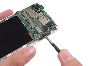
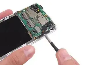
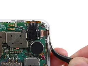
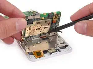
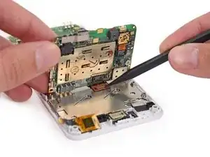
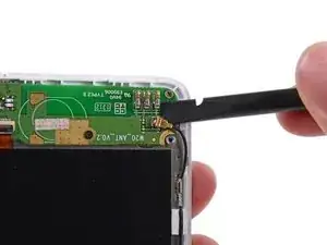
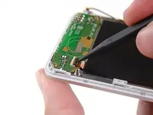
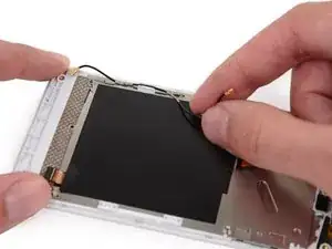
    • Use the tip of a spudger to flip open the tab on the daughterboard data cable ZIF connector.

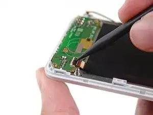
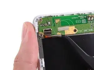
    • Use tweezers to pull the daughterboard data cable away from its socket.

  23. uZUWF6OSXOiGIZV1
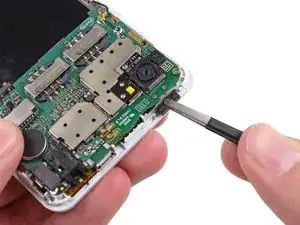
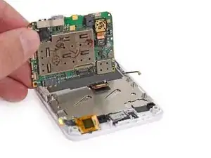
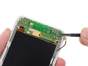
    • Remove the following screws securing the Wi-Fi daughterboard to the display assembly:

    • Two 2.5 mm Phillips #000 screws

    • One 1.6 mm Phillips #000 screw

    No "1.6 mm Phillips #000 screw" in my phone

    Erik Buelinckx -

    No One 1.6 mm Phillips #000 screw in Ynte's Fairphone.

    Inge -

    no one in mine either

    Koen Go -

    Not in mine either...

    Tijs Dekker -

    My Fairphone is also lacking the orange marked screw.

    Jan Boonen -

    Missing in mine too!

    elizabethnorseng -

    missing screw, too.

    [deleted] -

  24. oKGEbEDiqFT2T2Yb
    oKGEbEDiqFT2T2Yb
    T6dUEFhYrQ3Yy4Cr
    • The Wi-Fi antenna daughterboard is held to the front assembly by mild adhesive.

    • Use tweezers to gently pry the board up and remove it from the phone.

  25. XZFXBATB6wZjLimb
    XZFXBATB6wZjLimb
    NvSWaXbc5m4IdnOY
    haxMX4nCGMLFY5uQ
    • The earpiece speaker is held to the back of the display assembly with some mild adhesive.

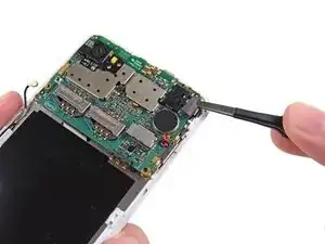
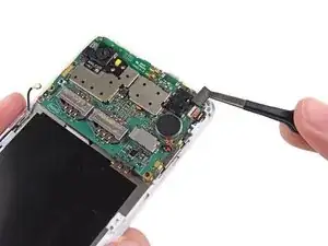
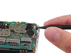
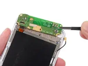
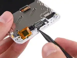
    • Use the tip of a spudger to gently pry the speaker up from the display assembly.

    • Remove the speaker.

    The earpiece speaker may have a 'rubber ring' glued to the front side. The new display assembly will probably have one of these already installed in the earpiece socket, covered with a protective orange ring. I peeled the old 'rubber ring' from the old earpiece, and then put the earpiece into the new display assembly. Old ring went back into the old display. But I guess you could put the new ring into the old assembly, and then you don't have to peel the earpiece apart...

    Tim Sparks -

    I somehow managed to break the speaker in this step (It was my first repair ever) .. Got a new one for less than 2€ at the fairphone parts shop, replaced it and it works now.

    Stefan Tzeggai -

  26. cAhwQdQEePVnAEt2
    cAhwQdQEePVnAEt2
    GcZbMSZOvsECFNGQ
    EX5Y24vsgcJc5Zk6
    • Remove the antenna interconnect cable from the display assembly.

    • The three sections of the cable with exposed metal fit into the grounding clips on the side of the display assembly.

Conclusion

To reassemble your device, follow these instructions in reverse order.

Jasper Fleischhauer

Member since: 20/10/14

33786 Reputation

0 comments