
Introduction
When the motor does not work, or only at FULL power, the triac is blown.
-
-
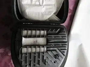
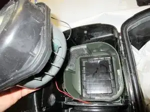
First pull the plug and roll on the Cable. Unplug the vacuumhose. Open the machine
-
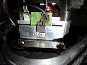
There are four PH2 Screws.
-
These screws all have the same length.
-
-
-
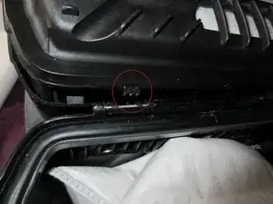
Look, there is the second clips from STEP 2
-
PULL.
-
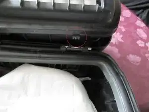
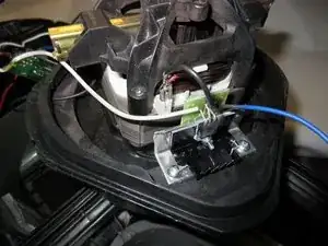
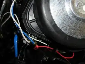
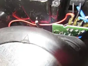
Open. Look, the white cable and the blue cable you have to remove there.
-
Blue cable and white cable have DIFFERENT SIZE OF PLUGS. it only fits right. ;)
-
-
-
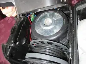
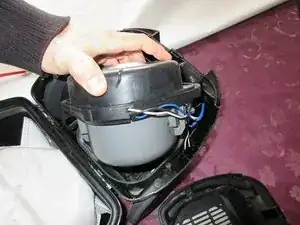
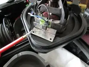
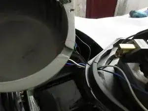
PULL the turbine,it has a stuck rubber case. Just PULL.
-
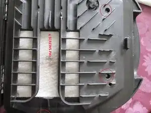
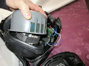
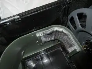
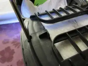
Then again, just pull, the grey Plasticpart. Look at the filters, they have to face eachother when you reassembel it !!! Marked in GREEN circles
-
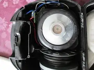
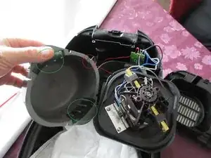
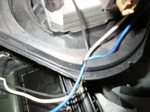
Look at red circle, there is a notch, there is where the White cable, the blue cable and the black cable go through the housing.
-
-
-
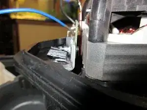
Detail of white cable and blue cable. The plugs have a small springholder, you must push and then pull off !!
-
The plugs have different sizes.
-
Unplug the short black cable at the motor. The plug has again a spring which should be pushed, then pull off teh black cable.
-
-
-
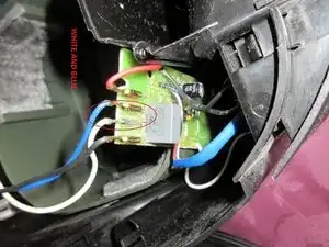
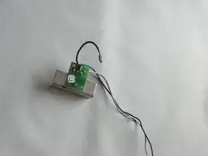
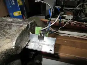
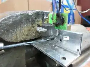
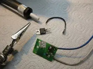
there you have it. The destroyed burnt TRIAC with cables and aluminium-cooling.
-
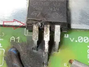
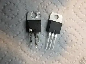
This one broke at the housing, look at the red arrow. The pins are bent directly at the housing, so this destruction occured at the montage of the triac ! bad. :( The current let it explode and damaged it complete.
-
cables look ok, platine is ok too. It looks burnt, but this is only black smoke.
-
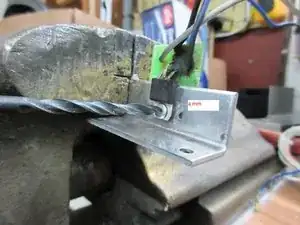
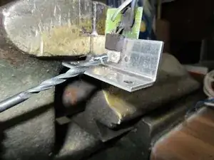
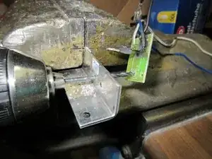
Now we have to drill out that part...
-
-
-
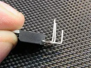
then pull the dead TRIAC up.
-
then you drill with 3 mm to get through the platine.
-
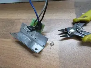
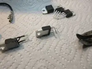
there you have it, all parts separated. :)
-
-
-
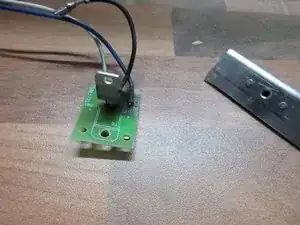
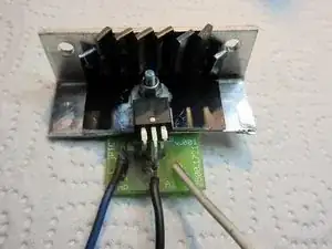
now desolder it. The platine has two holes which fit on the aluminium-cooler.
-
No problem with desoldering pump.
-
-
-
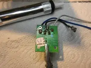
the new one.
-
follow the steps like on the pictures, i can't explain it, sorry. Like on the pictures, you can see, do it too.
-
-
-
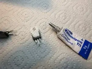
take some thermal componund. Only a very little amount.
-
take M3 screw, M3 washer and mount it to the aluminium-part.
-
solder the new part after the mechanical stress.
-
-
-
i made a cooling upgrade, you dont need to make this too because this is a DIY modification which is not really neccessary. XD
-
-
-
NOW REASSEMBLING
-
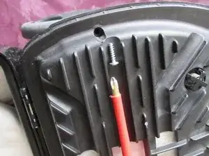
put it back, then you need the two SHORT ph2 screws.
-
Take care of the distance between the parts as shown on the third picture, i marked it with two red lines.
-
-
-
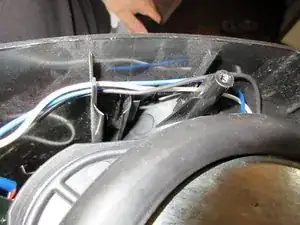
then put the white and the blue cable in place, there is also a second long black cable.
-
Look at the notch, it must fit right.
-
take care of the right fit of the filters there.
-
-
-
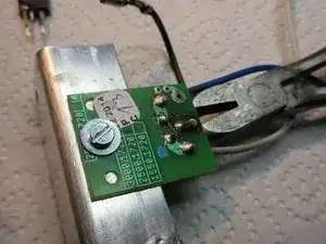
Detail of the cables.
-
There are notches to hold the cables.
-
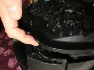
Lokk, there is a big notch in the platine of the third picture. RED CIRCLE. In this notch grips a latch of the housing when you close that part. Look at Steps 1 to 4 to see where you must take care of latches and notches and clipse.
-
-
-
Only when all parts fit equal together, all latches and notches and clips fit together and you firmly push down the housing, you can carefully screw in the 4 longer screws.
-
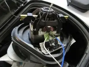
Test, function, done, now a Jägermeister.
-
:D
-
Only a few words, sorry, my english is bad, but i hope the pictures may help you.
-


Arbeite die Schritte in umgekehrter Reihenfolge ab, um dein Gerät wieder zusammenzubauen.
5 comments
Well, my child played with that Vacuum-cleaner and it overheated.
So I had to do this repairmanual for you.
Do not let play children with Machines. ;)
Just some comments for English speakers. I'm not dealing with spelling or awkward phrasing - I think it's clear emough. But for those that aren't sure on certain words, maybe this will help.
First tool listed is a #2 Philips-head screwdriver. So when you see PH2 screws, use your phillips screwdriver (also known as a cross screwdriver in some parts of the English-speaking world).
Step 2, middle bullet - "Pull, it knacks" literally would be cracks, which might sound negative. So "Pull, it does separate."
Step 4 (and elsewhere): turbine or motor.
Step 6, 1st bullet (& see Step 9 and elsewhere for variations) - (aluminium-)cooling or cooler = (aluminum) heat sink. [Americans don't use the 2nd i of aluminium.]
Step 6 (and elsewhere), 3rd bullet: platine = printed circuit board (I'll always refer to it as the PCB).
Part 2 of notes comes in my next comment --
J Stuart -
Part 2 of notes here --
Step 6, 2nd bullet [I know, out of order, but I wanted to use PCB, so translated it first] - Instead of translating it "The pins are bent directly at the housing, so this destruction occured at the montage of the triac !" I would've said "The pins are bent to go into the PCB, and the destructive forces inside the triac caused the assembly ("montage") to burst open at the other end of the pins, where they enter the triac housing!"
Steps 7-8 - there is a rivet that goes through the triack, then through the heat sink, then through the PCB. For getting the rivet out, you drill with a 4mm drill bit through the rivet head, through the triac mount, and lift the triac out of the way, then continue very carefully through the heat sink. Now the PCB can be removed from the heat sink. Then switch to a 3mm bit and drill the remnants of the rivet out of the PCB.
Part 3 coming up --
J Stuart -