Introduction

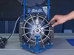
This guide demonstrates how to remove or replace the left lower feeder assembly in the auto-feeder on your Electric Eel 75’ Drain Cleaner Z5K12IC75AF.

If you need to remove or replace the right lower feeder assembly, simply perform steps 12-17 on the opposite side of the feeder body.

  1. P4lTpgLwLEUKfkiB
    P4lTpgLwLEUKfkiB
    LUIHdnyOdY3GBsjd
    6TZvZ2tyGLxDVWvv
    • Unplug your drain cleaner before starting this guide. Because this device may have been used in a septic setting, it should be cleaned and disinfected as much as possible before disassembly.

    • Wear gloves to protect your hands from injury when handling the cable.

    • Ensure the cable is completely retracted into the auto-feeder.

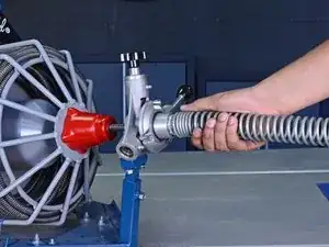
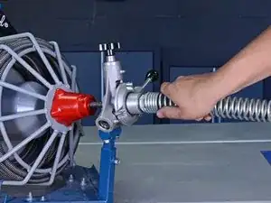
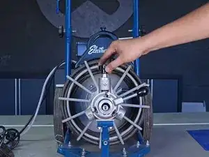
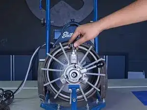
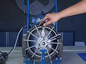
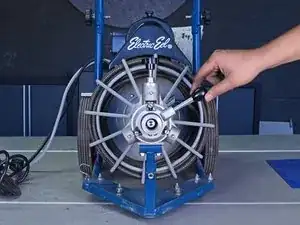
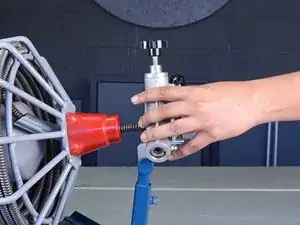
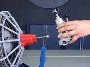
    • Twist the guide spring counter-clockwise to unscrew it from the auto-feeder.

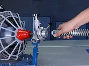
    • Remove the guide spring.

  2. davZ6vQZJJ5grSSh
    davZ6vQZJJ5grSSh
    W5AVMwWZWfQFn3iM
    JZmIOIgDmUOTNPrj
    • Unscrew the tension knob to loosen the tension spring in the top feeder assembly.

  3. ArKKXVtRdPkjnbm1
    ArKKXVtRdPkjnbm1
    fRpgnqxyCKh2nROA
    S3RmJrh2lOBV4pmA
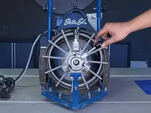
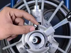
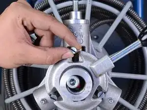
    • Set the feeder adjustment knob in the neutral position, in between the "FWD" and "REV" positions.

  4. BTlRN3kcb6TAgRGg
    BTlRN3kcb6TAgRGg
    vFvdrabPlfStShsT
    • Push the top control finger up as far as possible.

    • This disengages the top feeder assembly and allows the cable to freely move through the feeder. The finger may fall back down on its own and restrict cable movement. If this occurs, simply push the finger back up.

  5. FFBv3prAfCYGwOye
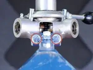
    • Use a 1/2" open-ended wrench to remove the two bolts from the bottom of the feeder body mounting arm.

  6. WERZXKK6k3bPN5H6
    WERZXKK6k3bPN5H6
    jtBJlo1wdDAnJQci
    • Remove the auto-feeder from the cable.

    • If the end of the cable won't pass through the feeder, ensure that the top bearing is completely disengaged as described in step 4 of this guide.

    Now yo have the head off. You need to remove the bearing. Snap ring pliers. Then unscrew the flat head screw. The bearing holder should slip out and then you are done.

    PART NUMBER IS DE-10SET

    REPLACE ALL 3.

    Mark W -

  7. VeSYpC42Rx6bsbIJ
    • Use a vise to compress the roll pin until there is no longer space in the roll pin's slot.

  8. yJd2JFoEwFdYA4tB
    yJd2JFoEwFdYA4tB
    AI5EHhlRGrEcQRIr
    bbPpNk5v2CfpJuOJ
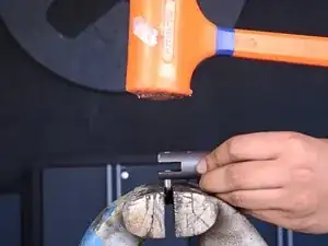
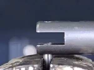
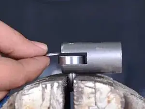
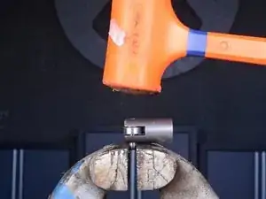
    • Use a dead blow hammer or mallet to tap down the bearing carrier onto the roll pin until the pin just begins to peek into the bearing channel.

    • Ensure you are using the correct bearing carrier for this step. The top bearing assembly uses the shorter carrier, while the two lower bearing assemblies use the longer carrier.

  9. LWnSBtaAUxg4dVPs
    LWnSBtaAUxg4dVPs
    PoSGtTKGIudBO5FB
    TKaB6vvxARjZdlr2
    • Insert a bearing and the bearing spacer into the bearing channel.

    • Ensure that the bearing and spacer are aligned with the roll pin and hole in the bearing carrier.

  10. AcfpBXKNl55UHCVo
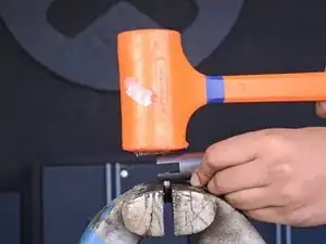
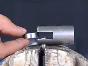
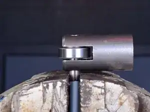
    • Continue to tap down the bearing carrier until the bearing and spacer are fully secured around the roll pin.

    • You will need to unclamp and reposition the roll pin upwards to continue tapping it into the bearing carrier. Do this as many times as is necessary to sufficiently support the roll pin.

  11. c3sPheuFM6WDqQHu
    • Use a roll pin punch to finish seating the roll pin into place.

    • Place a piece of cloth or mat on top of the vise below the bearing carrier to prevent marring the outer surface of the bearing carrier.

    • Before moving to the next step, ensure the roll pin is fully seated and completely within the bearing carrier. A slightly exposed roll pin may damage the inside of your feeder body when the bearing carrier assembly is being installed.

  12. 5gaPNvqV1Q1MZeJP
    5gaPNvqV1Q1MZeJP
    5KCdUfJyhA3kpw2q
    mYbpUtUxsyLm1isX
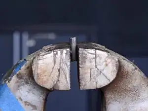
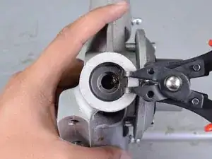
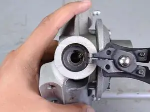
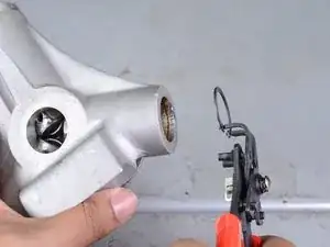
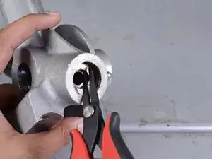
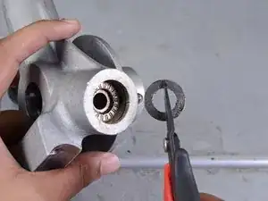
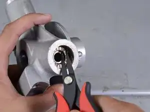
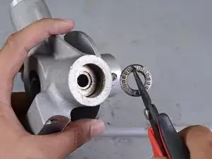
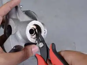
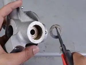
    • Use a pair of snap ring pliers to remove the retaining ring at the bottom of the lower feeder assembly.

  13. UIMj1kjJDYVlwTmR
    UIMj1kjJDYVlwTmR
    Ru3DebNlcCUt5my2
    • Use a pair of needle-nose pliers to remove the first thrust washer from the assembly.

  14. UKFACajw3OPXsK5A
    UKFACajw3OPXsK5A
    FQNVHyrfdA2U2Ind
    • Remove the thrust bearing from the assembly.

  15. HVDiyBXg61PnstOT
    HVDiyBXg61PnstOT
    FklXn5O3Nt3JQjBH
    • Remove the second thrust washer from the assembly.

  16. RROxFIWD2qO2aVNU
    • Use a flathead screwdriver to remove the lower control finger from the assembly.

  17. miXDKUpI4QnnSKAj
    miXDKUpI4QnnSKAj
    Vv2oVVI5eHAxYR5P
    fPwfbjAbLYxhTn5K
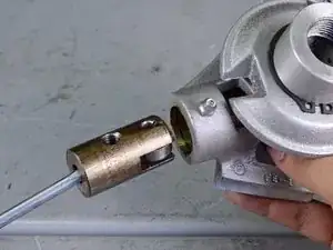
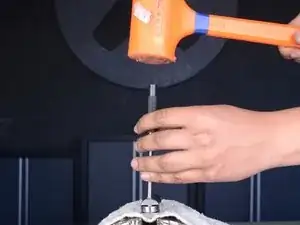
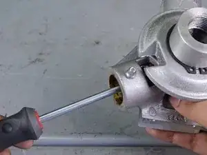
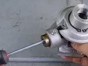
    • Use a flathead screwdriver or other long tool as leverage to remove the lower bearing carrier from the assembly.

Conclusion

To reassemble your device, follow these instructions in reverse order.

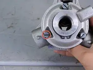
After reassembly: Ensure the assembly you just installed is sufficiently lubricated using the Zerk fitting on the feeder body.

Tarun Thiruma

Member since: 20/11/19

35226 Reputation

0 comments