Introduction

This guide has been updated by iFixit staff! Read the new, official guide here.
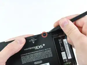
  1. g6dlRVZpjEeBlDqS
    • Loosen the two screws on the battery panel. Then lift the panel up to remove it.

  2. ZKKCp1kR1lAijwch
    • L Button.

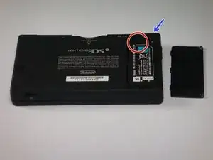
    • Top of the battery pack.

    • To remove the battery pack, place your fingernail or a spudger at the top of the battery near the L button. Gently lift the battery out.

    That's great. WHAT ABOUT THE THREE OTHER SCREWS KEEPING THE BACK ON!?

    tekgeekster -

  3. ZElvjs4G5DRnVKEX
    ZElvjs4G5DRnVKEX
    NNd3fYSswNeKCoBU
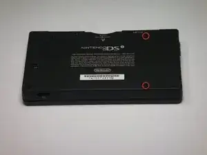
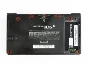
    • Two screws are hidden underneath two rubber feet highlighted in red.

    • Use the tip of a spudger to pry the rubber feet out of the lower case.

    • Depending on the age of your device, the rubber feet may crumble apart as you pry them out. If so, use a fine-tipped tool to scrape out any stuck pieces of rubber.

    One of the feet did break on me, tweezers came in handy for picking it out

    Willie Narvaez -

    I unfolded and sharpened a paperclip. You can use that to stab and hook the rubber without tearing it, as the rubber is thick enough to reseal when reinserted.

    Keegan Andersen -

    Nasty, broke my spudger and the feet in this step.

    TimedIn -

  4. MPpnnO22qoYDH1YH
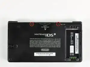
    • Remove the following screws securing the lower case to the body of the DSi:

    • Six 5.2 mm Phillips #00 screws.

    • One 2.7 mm Phillips #00 screw.

    Impossible d'enlever les vises… trop serré! comment faire?

    evrobert03 -

    i can't get the screw by the gamecard slot out, PH#00 is too small and PH#0 is too big

    Iblowup -

    same problem here. maybe try a JIS?

    darth mango -

  5. MqTKErbDcomH6eMJ
    MqTKErbDcomH6eMJ
    HuePUMK6TciCQZEj
    OkwvvvtBbd53ugBG
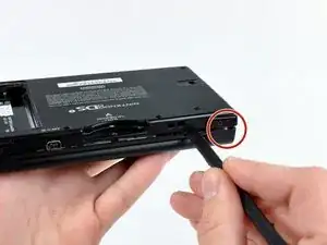
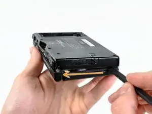
    • Insert the spudger in between the lower casing and lower panel near the top right corner of the DSi.

    • Carefully run the spudger along the edge of the outer casing, creating an opening between the body and the casing.

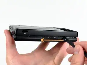
    • Continue running the spudger around the body of the DSi until the majority of the lower case has been separated.

  6. ZsX1F2YxXpOFEtuH
    ZsX1F2YxXpOFEtuH
    BS25HSFVrSclu2X1
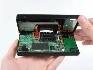
    • Carefully lift the lower casing from its bottom edge.

    • The lower case is still attached to the motherboard by the volume and SD board cable highlighted in red. Do not try to completely remove the lower case of the DSi yet.

    • Pry the volume and SD board cable up from its socket on the motherboard using a spudger.

    • Once the cable is completely removed, then you may take off the entire outer casing.

  7. 2hFHQUOkvfPbdJvR
    • Flip up the black latch and disconnect the D-Pad/Power Button ribbon cable.

  8. dWEpZmQDsygLDOZ1
    dWEpZmQDsygLDOZ1
    OoMrHJOHvhlOBuXt
    QuRDPRr2GOeRAOWs
    • The power connector (with red and black wires) is difficult to remove without damaging it, unless you take a moment and understand how it works. Look at all of the photos for this step before continuing.

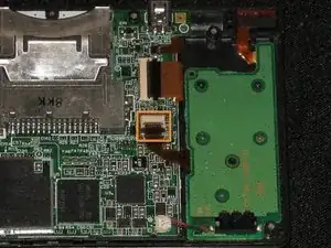
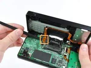
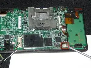
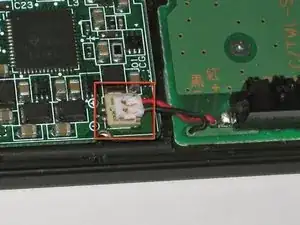
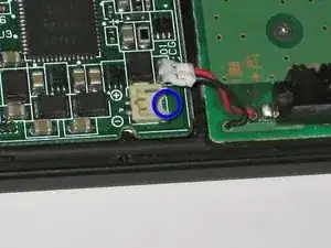
    • The connector is two pieces -- a white "male" piece (connected to the wires), and a beige "female" part (soldered to the main board).

    • There is a small "notch" in the female part, to give you a place to insert a small flat-head screwdriver. Put the corner of your screwdriver in there, and twist it gently to push the white part up (away from the main board). Do not try to pull it to the right (towards the battery board).

    • If it does not lift easily, try again with a smaller screwdriver. You might be pulling the female connector off the board, which will be difficult to repair.

Conclusion

To reassemble your device, follow these instructions in reverse order.

bushing

Member since: 24/04/10

10244 Reputation

0 comments