
Introduction
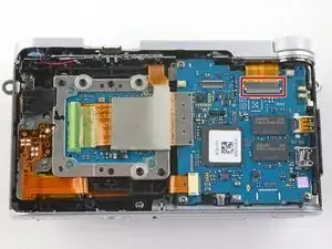
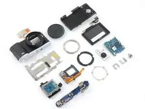
This guide gives you a look at the major components of the Samsung NX3000 and provides complete disassembly instructions.
We highly suggest you use a magnetic project mat or an organization tray. This camera has many different types of screws and keeping them organized is key to proper reassembly.
-
-
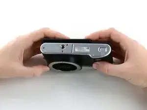
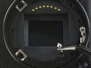
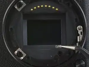
Turn the camera upside down. Only remove the lens if you have to in order to access the battery compartment, as dust particles could easily enter the main body and fall onto the delicate sensor.
-
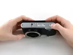
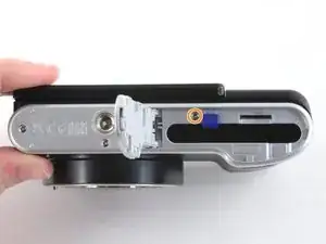
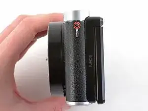
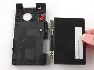
Slide the button to the left to open the battery compartment.
-
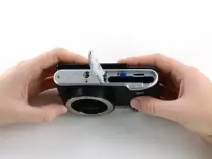
Push the blue button up to release the battery.
-
-
-
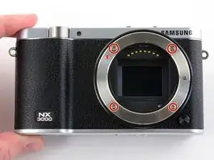
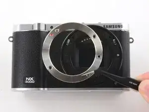
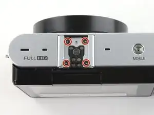
Remove the four 7.3 mm Phillips screws from the front of the lens assembly.
-
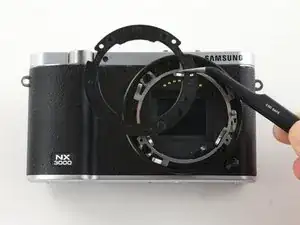
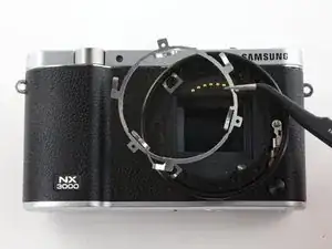
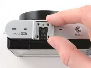
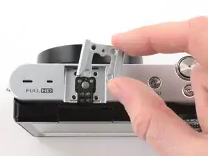
Remove the silver ring with tweezers.
-
-
-
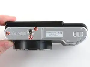
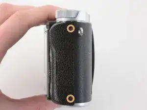
Remove the three 4.3 mm Phillips screws from the bottom of the camera.
-
Remove the 4.3 mm Phillips screw hiding inside the battery compartment.
-
-
-
Remove the 4.2 mm Phillips screw from the left handgrip.
-
Remove the two 4.2 mm Phillips screws from the right handgrip.
-
-
-
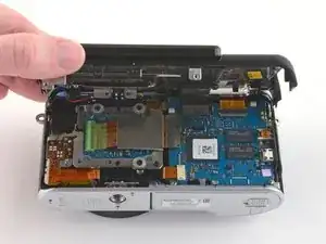
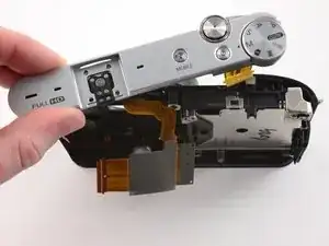
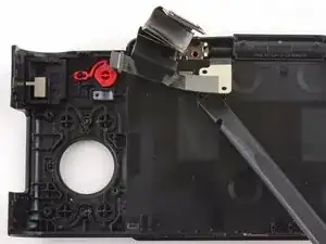
Use the flat end of a spudger to pry the flat topped connector straight up from the motherboard.
-
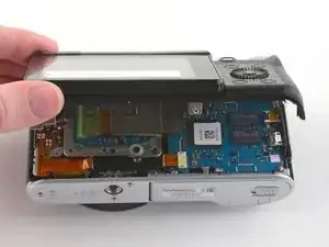
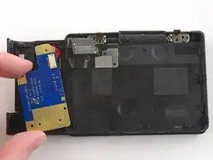
Remove the back case.
-
-
-
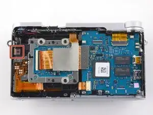
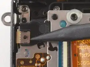
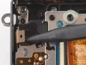
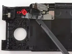
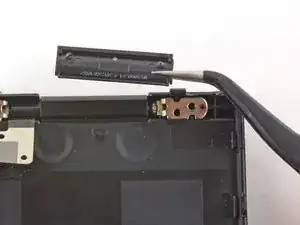
Use the pointed end of a spudger to lift the ribbon cable straight out of the black clip located near the left handgrip.
-
-
-
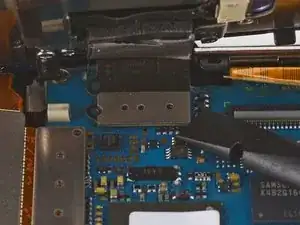
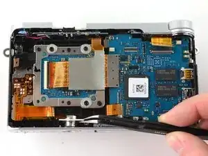
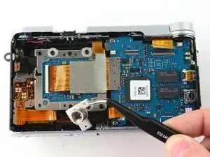
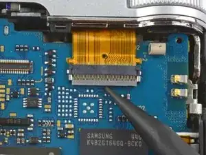
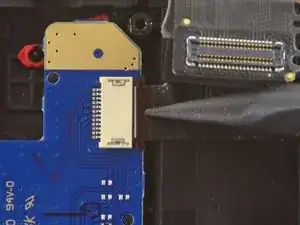
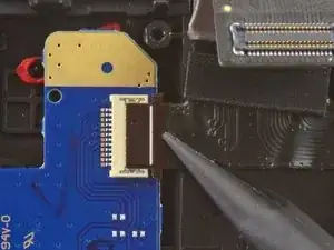
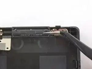
Use the flat end of a spudger to disconnect the large ribbon cable by prying its metal connector straight up from the motherboard.
-
-
-
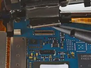
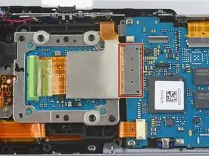
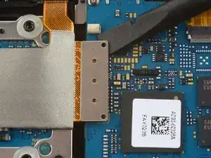
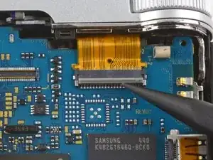
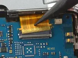
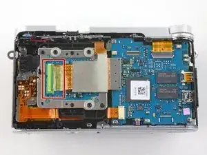
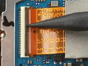
Use the pointed tip of a spudger to unlock the ZIF connector by flipping the black bar straight up from the motherboard.
-
-
-
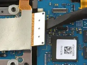
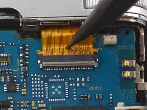
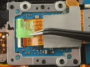
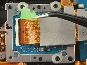
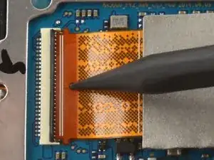
Insert the pointed end of a spudger into the hole on the ribbon cable.
-
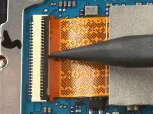
Pull the ribbon cable straight out of the ZIF connector.
-
-
-
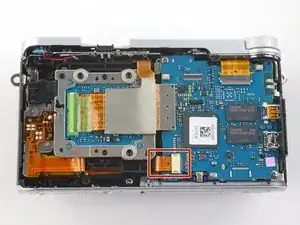
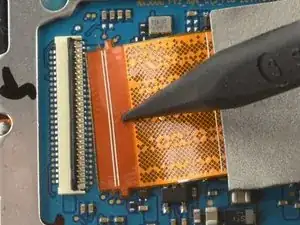
Insert the pointed end of a spudger into the hole on the ribbon cable in the bottom left corner of the motherboard.
-
Pull the ribbon straight out of the connector.
-
-
-
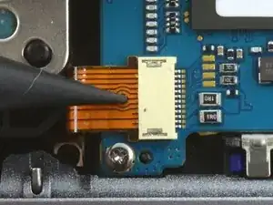
Use the pointed tip of a spudger to flip the black bar on the ZIF connector straight up from the ribbon cable.
-
-
-
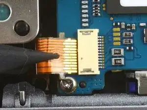
Insert the pointed end of a spudger into the hole on the ribbon cable.
-
Pull the ribbon cable straight out of the connector.
-
-
-
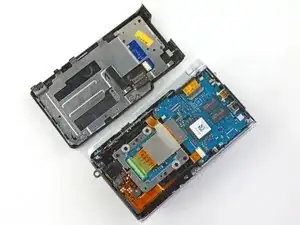
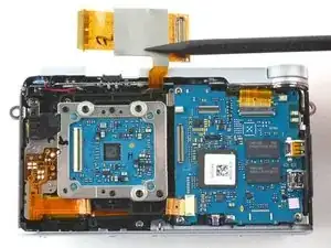
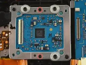
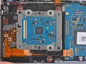
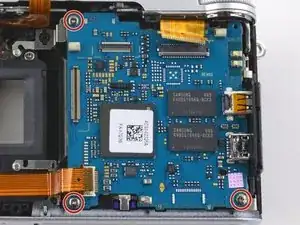
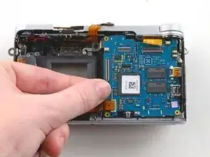
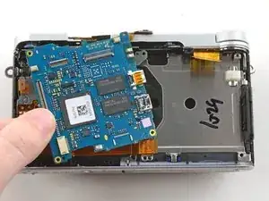
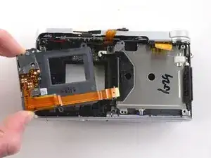
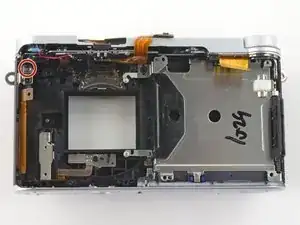
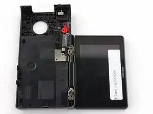
Remove the three 4.3 mm Phillips screws from the motherboard.
-
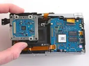
Remove the motherboard from the camera.
-
-
-
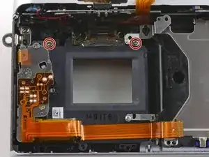
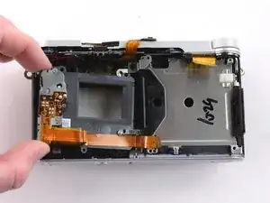
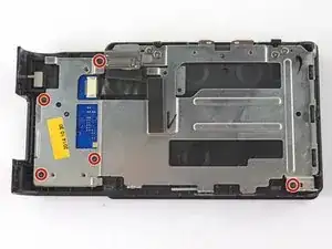
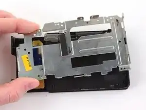
Remove the two 5.3 mm Phillips screws holding the sensor frame to the case.
-
Remove the sensor frame.
-
-
-
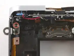
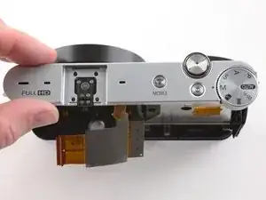
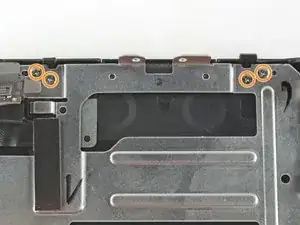
Remove the 4.3 mm Phillips screw in the upper left corner that secures the top plate to the front case
-
-
-
To remove the metal shield on the back case, remove the following screws:
-
Five black 4.2 mm Phillips screws .
-
Four silver 5.3 mm Phillips screws.
-
-
-
Use the pointed end of a spudger to remove the ribbon cable attaching the button panel to the back case.
-
Remove the button panel.
-
-
-
Tilt the LCD so it lays flat against the back case.
-
Wiggle the LCD joints and pull the LCD away from the back case.
-
To reassemble your device, follow these instructions in reverse order.

9 comments
Excellent photo documentation.
Thank you ernestliasa!
Where can I found the camera's microphone?
Hi dude. I did all the steps and disassembled the camera and I removed the IR filter from the sensor. All is good until that point. And then I assembled the camera in reverse order but now there is no display on screen. In my first attempt I got the menu working but I got no live view display or photo. Then I re-opened and assembled again. This time there is just nothing. Camera turns on but no display, no messages. the zoom button, on/off and even the video record button works all well but no display.. Any thoughts on this pls?
PS: This is an excellent tutorial by the way. I must have done smth. wrong, otherwise I had no issues on disassembly.
edayi -