Introduction

  1. jfPT1Cf6JsaHUHaL
    • Before you begin, be sure to turn off your laptop and unplug it from the outlet.

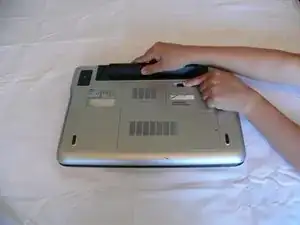
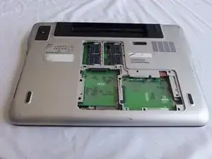
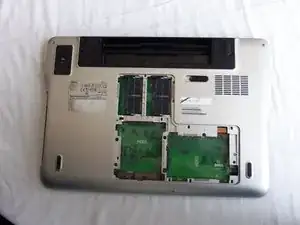
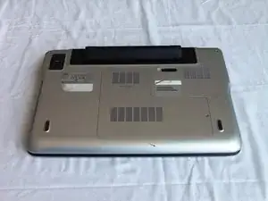
    • Flip over the laptop so that the bottom battery compartment faces upwards.

  2. YBZNKNVPovKGFDWT
    YBZNKNVPovKGFDWT
    bR4QfReUIfnn3HgE
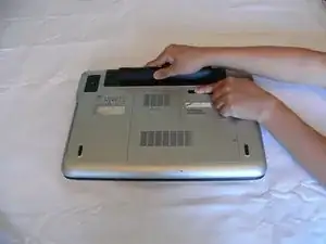
    • Slide the tab below the battery to the left and hold the tab in place.

  3. udfnn152x2N3aHtP
    udfnn152x2N3aHtP
    IAK3liKpDeZn4SeR
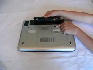
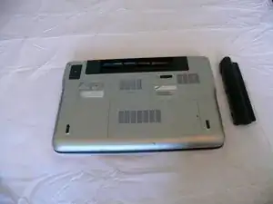
    • While holding the tab, lift the battery out of its compartment.

    • Release the tab after removing the battery.

  4. mWo4xHFn5APmfu6J
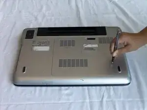
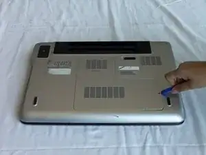
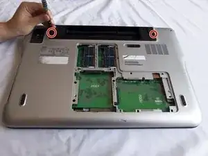
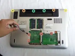
    • Loosen the module cover screw with a Phillips screwdriver.

    • The screw is attached to the cover; do not force it out.

  5. krAm1Cl243POo1qq
    krAm1Cl243POo1qq
    jhxmydrXB6eHHZtg
    eQutG5RyWfxZ1uhF
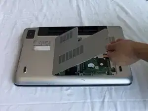
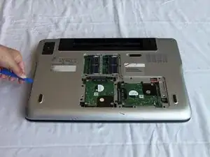
    • Lift the module cover by inserting a plastic opening tool into the crevice near the screw and lift upwards.

  6. rMnbBfcSoofLSrLf
    rMnbBfcSoofLSrLf
    nujXxgeZupcfEYFR
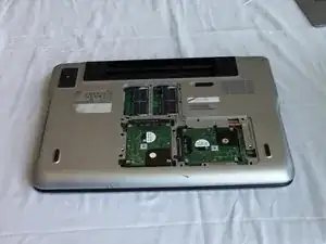
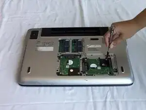
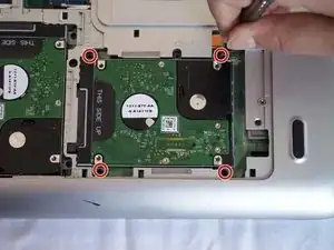
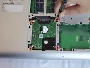
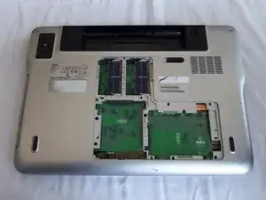
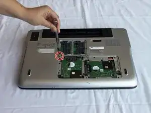
    • Remove the four 4mm Phillips screws fastening the first hard drive.

  7. JaBAlYnSoplpybIf
    JaBAlYnSoplpybIf
    ceqIFalBwFQttAUi
    VKYExHVUtOKZCUcb
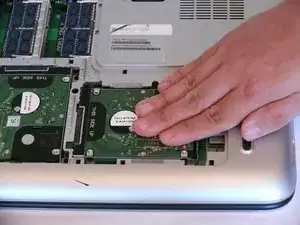
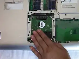
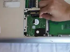
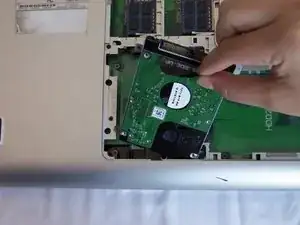
    • Slide the hard drive with your hand towards the hole where the back panel assembly screw was located (in step 5) to disconnect it.

    • Lift the hard drive up to remove it from the case.

  8. L5RrlVGQAwKcxr3o
    • Remove the four 4mm Phillips screws on the second hard drive.

  9. q4aakHJyXRDvXVYF
    q4aakHJyXRDvXVYF
    GXwDxFFAXFOGQY62
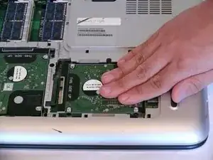
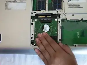
    • Slide the hard drive towards the edge nearest you to disconnect it.

  10. 1UZws2NgsULRfN4j
    1UZws2NgsULRfN4j
    M2WYYDXHcymFY1uD
    PNZAKfCfjcZg1Aam
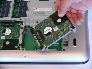
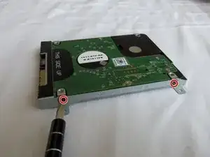
    • Using the tab that says "THIS SIDE UP," pull away from the laptop to remove the hard drive.

  11. 5MvidoXXORrTMGWv
    5MvidoXXORrTMGWv
    FsxxDJuVdCeViduU
    • Repeat this step for each hard drive.

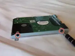
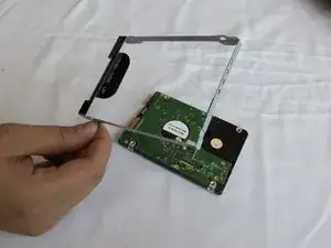
    • Unscrew the two 4mm screws from each side of the hard drive casing with a Phillips screwdriver.

  12. kQosSfHAHfcdIkbx
    • Remove the hard drive casing.

  13. UeDdDPhLnZwAtYwL
    • Unscrew the screw holding the optical drive with a Phillips screwdriver.

  14. kyxGWi4gWqKgy6GJ
    kyxGWi4gWqKgy6GJ
    3wQhwfilCxMLXUmX
    hHNcah1VL5iABWRr
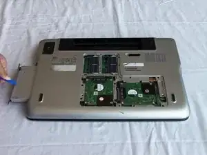
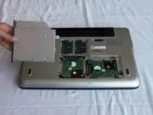
    • Using a plastic opening tool, pull out the optical drive.

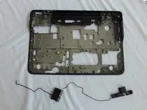
  15. XPMoktEL6mucXv5c
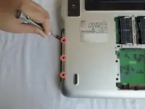
    • Unscrew three 4mm screws near the edge of the optical drive compartment with a Phillips screwdriver.

  16. ZvQkyn3ELIhKIJAW
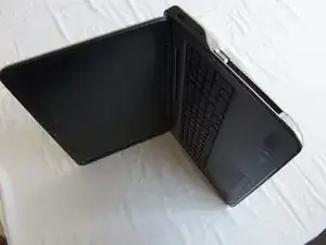
    • Open the laptop to about a 90 degree angle and place it on its side with the empty optical drive slot pointing upwards.

  17. opMBYICo3OiggSYY
    opMBYICo3OiggSYY
    hPqR4UV5QGRfgLON
    4FZGZfunKTEaMUe1
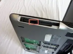
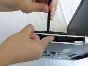
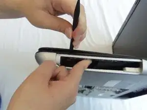
    • Push and hold the tab inside the optical drive's opening with your index finger.

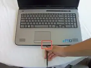
    • Insert a spudger between the black and silver plastic pieces that are above the tab and pry apart the two pieces.

  18. abwC3MFh3MErhGjY
    abwC3MFh3MErhGjY
    2uRNq6f23YdOXfrK
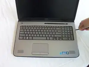
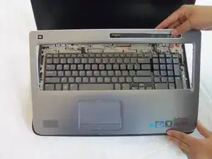
    • Slide the spudger around the palm rest to release the clips.

    • You may hear a crackling noise; this is normal.

    • Use caution when sliding below the mouse pad, as there are wires we must detach in the next steps.

  19. JwGlRqpgcgDgiTKK
    JwGlRqpgcgDgiTKK
    2ljRWm3rKmtuma5s
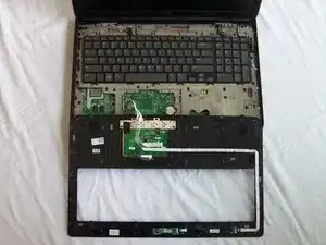
    • Gently lift and rotate the palm rest panel until it's upside down as it is still connected by the mouse pad wires.

    • The mouse pad wires are still connected to the palm rest panel.

  20. BO4L1RBHAFYM34eu
    BO4L1RBHAFYM34eu
    CovkQsKFX1ErrDYA
    jlEOewP3EZXKTIJD
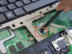
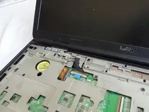
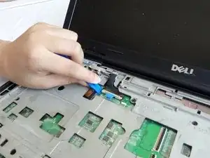
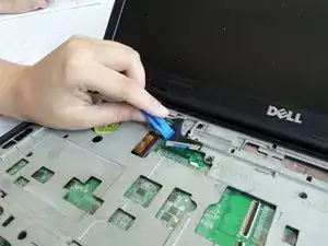
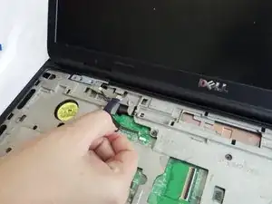
    • Put the spudger below the black tab of the wider cable and push up to release.

    • Gently pull out the cable.

  21. TjZBanAQXExIbPir
    TjZBanAQXExIbPir
    wLO5aGUUV2iK4KU6
    6lAmll2cBXUxJZpT
    • Insert the spudger below the black tab of the remaining cable and push up to release.

    • Gently pull out the cable.

  22. hgYrMIRuBDGbZSJQ
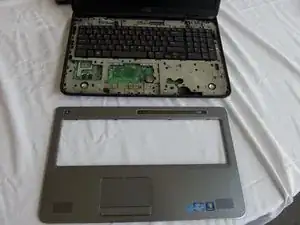
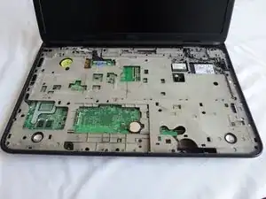
    • Remove the palm rest from the laptop.

  23. 4mAh4bJDQFJ6H1ZC
    4mAh4bJDQFJ6H1ZC
    O1xof6BsYbWNmSkh
    bUM3wUAKfEZe2tKy
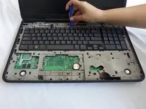
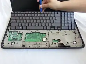
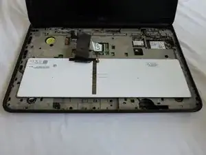
    • Using the plastic opening tool, slightly lift and rotate the keyboard until it's upside down from the display side of the laptop.

    • DO NOT lift the keyboard all the way up as there are wires that are still connected.

  24. pEwX1NhKKQwSOD6K
    pEwX1NhKKQwSOD6K
    mipn2hLLMHYqplrl
    HoZUaGteIY2niP1y
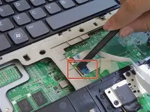
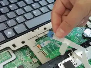
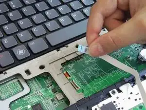
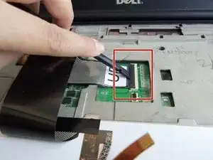
    • Gently insert the spudger below the edge of the black tab of the thin, copper colored cable and pry it open.

    • Gently pull out the cable.

  25. rydQB3VqoiVG1Zye
    rydQB3VqoiVG1Zye
    HZjDsOvweLqxSjET
    HFkgNBCPbQEKLGaI
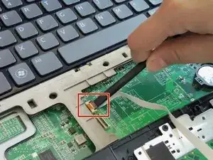
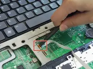
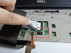
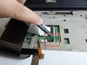
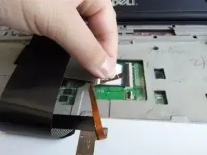
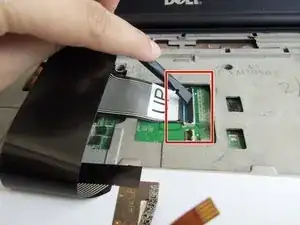
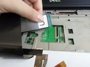
    • Gently insert the spudger under the edge of the black tab of the cable marked "UP" and pry it open.

    • Gently pull out the cable.

  26. KuVXUjQEbDUdPU3S
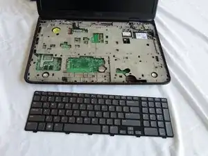
    • Remove the keyboard from the laptop.

  27. FWqbRkhLfgxHsbfA
    FWqbRkhLfgxHsbfA
    JM6XPLWw6jkDFSQo
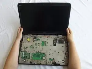
    • Close the display, and flip the laptop over so that the bottom faces upwards.

    • Remove the two 16 mm screws with a Phillips screwdriver.

  28. fOZmlH2xFfJIEZta
    • Gently flip over the laptop and open the back cover assembly.

  29. 2tfLiNlY1DnHATVB
    2tfLiNlY1DnHATVB
    ZK2LjVRmPtXOnlVB
    353VB2tY2S3qunR4
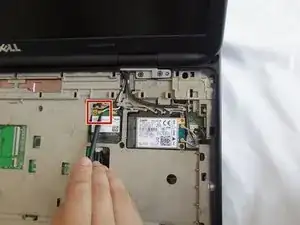
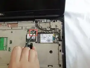
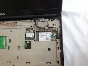
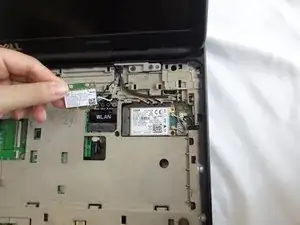
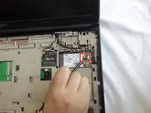
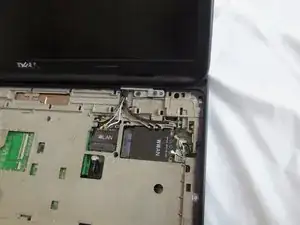
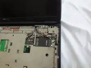
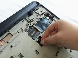
    • Insert the pointy side of the spudger below the golden connector of the white cable on the WLAN card and lift to detach.

    Be very careful! Just pulled one of the connectors off the WLAN card

    Chris Geffen -

  30. 3JT2V2yKZGSGmbNq
    3JT2V2yKZGSGmbNq
    YvoVnbi1jbKO1jSF
    6SB3h12deIXuryMx
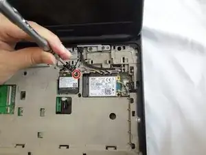
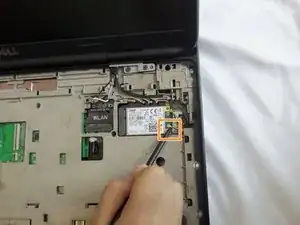
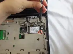
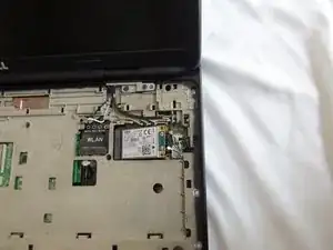
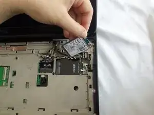
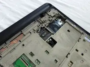
    • Unscrew the 4mm screw from the WLAN card with a Phillips screwdriver. The card will lift itself after you remove the 4mm screw.

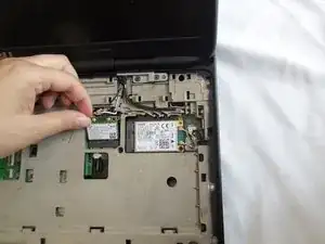
    • Gently pull out the WLAN card.

  31. wQePQKiaW3FQaKrV
    wQePQKiaW3FQaKrV
    XUBMM6DfIt2KyPB4
    knbSDHIPuTGFkvDf
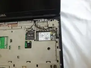
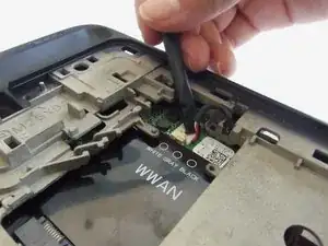
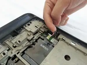
    • Insert the pointy side of the spudger below the golden color connector of the gray cable on the WWAN card and lift to detach.

    • Insert the pointy side of the spudger below the golden color connector of the black cable on the WWAN card and lift to detach.

  32. HpDe1X1hANlDuQhW
    HpDe1X1hANlDuQhW
    FVprTZTkOweGnOZb
    fHu4LQPpbpUQXrBT
    • Unscrew the 4mm screw from the WWAN card with a Phillips screwdriver. The card will lift itself.

    • Gently pull out the WWAN card.

  33. arVUytQwwBGTRsDK
    arVUytQwwBGTRsDK
    kLTGxIB4aAPWcRJY
    aErBYIJuHWIyUYG4
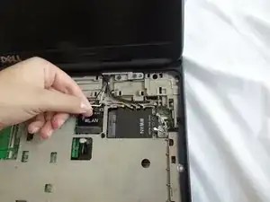
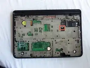
    • Gently remove the wires for the WLAN and WWAN cards from their housing.

  34. 6cwoEuVxP4klOHZG
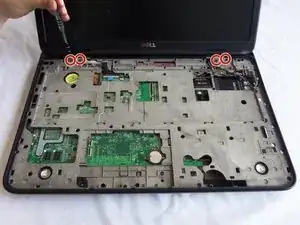
    • Unscrew four the 8mm screws directly under the keyboard with a Phillips screwdriver.

  35. d3ujNZTZKOJkjvnn
    d3ujNZTZKOJkjvnn
    YstTfJKHZ3lNRTDp
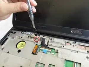
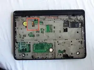
    • Loosen the grounding screw attached to the black monitor cable with a Phillips screwdriver.

    • DO NOT ATTEMPT TO REMOVE THE SCREW FROM THE WIRE. The screw is permanently fixed onto the wire.

  36. DNLVQFCDGGy2KQaC
    DNLVQFCDGGy2KQaC
    cMHj6WwVcLBIQxDf
    • Using the plastic opening tool, detach the connection from the cable to the board.

  37. fSotoLZIEKQH6uLA
    • Gently remove the monitor cable from its holdings from the board.

  38. UsBULZ2upJLrV3QU
    UsBULZ2upJLrV3QU
    LrXgS4OCOZjIWG3S
    45ITwvIFjFbrXKOI
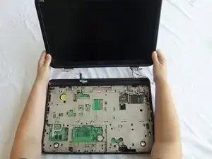
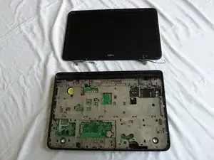
    • Hold the plastic edge of the display firmly and lift to remove the display.

  39. RQWSEeXsg2CVnSpV
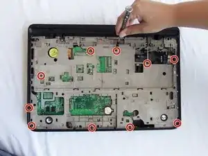
    • Unscrew the ten 8mm screws from the grey inner casing with a Phillips screwdriver.

  40. nwlcuS3gWkSgqNFU
    nwlcuS3gWkSgqNFU
    HnkEafIQZKBbSfRh
    1lRRLbjSuUMQOHFZ
    • Locate the sound card cable.

    • Gently unplug the sound card cable.

  41. AQLsTWNsw4ZVTSk2
    AQLsTWNsw4ZVTSk2
    vadnLrsCtbse4NPQ
    vkiHHHKVDNGDnSfQ
    • Find the orange cable with the letters MB.

    • Gently insert the spudger below the edge of the black tab and pry it open.

    • DO NOT attempt to pull out the cable on this step.

  42. f5iWMOFFLydC3TYO
    f5iWMOFFLydC3TYO
    gahYZWeFGHRFOUpR
    CgtiffteEBMIpeXi
    • Locate the wire on the side of WWAN slot.

    • Using the spudger, gently pull out the cable.

  43. kPpNXhJdapJnxlXE
    kPpNXhJdapJnxlXE
    GcuRRIiDNnOeZIYd
    • Gently flip the laptop with its bottom facing you.

    • Remove the four 8mm screws with a Phillips screwdriver.

    • Remove the two 16mm battery casing screws with a Phillips screwdriver.

    • Remove the two 16mm corner screws with a Phillips screwdriver.

    • Remove the two 4mm screws inside battery housing with a Phillips screwdriver.

    • Removing the RAM is optional. This guide does not cover the removal of the RAM card.

  44. 22XVJJNfVSf26cbj
    22XVJJNfVSf26cbj
    CoZJw2jHDRjswrFP
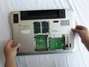
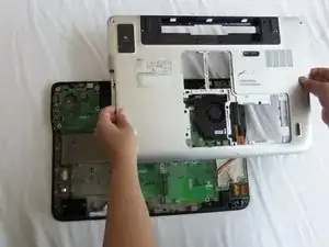
    • Holding the opening from the optical drive in one hand with the other hand holding the opposite side of the laptop, lift and remove the back cover assembly.

    Make sure you remember to remove the SD card cover before pulling off the back cover

    watercannons -

  45. xsACskbqaidwiYaG
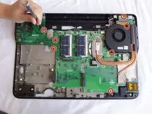
    • Unscrew the seven 4mm screws with a Phillips screwdriver.

  46. 4rKoFUQGrPCEZdXN
    4rKoFUQGrPCEZdXN
    rDAU2QXCDxOygCbY
    6IJUK2d6ReIXWYXi
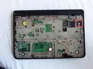
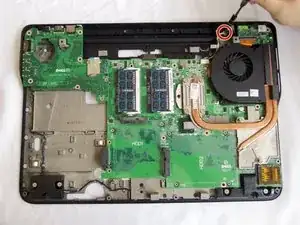
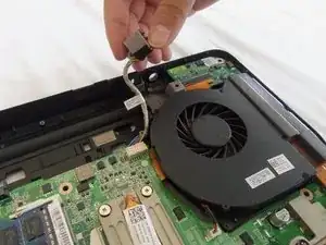
    • Unscrew the 6mm screw on the DC cable assembly with a Phillips screwdriver.

    • Lift the DC cable assembly out of the casing.

    • Gently unplug the DC cable.

  47. oKTm2AvWbjCsVXnA
    • Lift and remove the Wi-Fi circuit board.

  48. OHcfK35JCyOG2vQc
    OHcfK35JCyOG2vQc
    mrrHGLMdFJkYdRdk
    ADIs5NwbAp1IrIO1
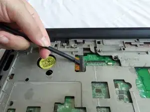
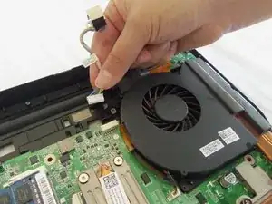
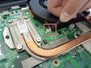
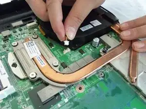
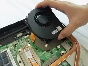
    • Gently use a spudger to pry off the fan power cable.

    • Lift and remove the fan.

  49. MmtnUSUTOycXNaXU
    MmtnUSUTOycXNaXU
    4ZpYiHbPRFrHx5wL
    wslLFoQIDHXDRvS2
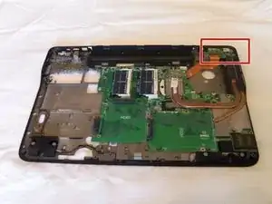
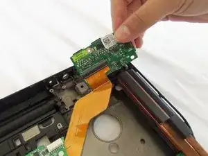
    • Lift and remove the USB circuit board out of its housing.

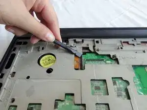
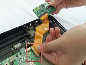
    • Remove the orange cable from the motherboard by gently pulling away from the connection point.

  50. hDJZGEoHGCEEyOqE
    hDJZGEoHGCEEyOqE
    EsJguPTnY5JBQDlC
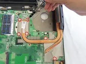
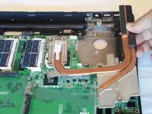
    • Loosen the six screws with a Phillips screwdriver.

    • The screws are attached to the heat sink piece. Do not attempt to remove them from the heat sink assembly.

  51. ZyUAN63r56SM466T
    ZyUAN63r56SM466T
    vfuDGfVDDECZDjjP
    gJgwdBf2eYgAMxov
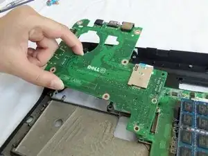
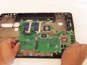
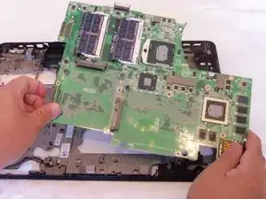
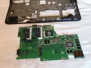
    • Gently lift and remove the motherboard.

    • Clean the thermal paste with rubbing alcohol and a microfiber cloth or non-abrasive tissue.

  52. yQOhRr2FbrBdrinK
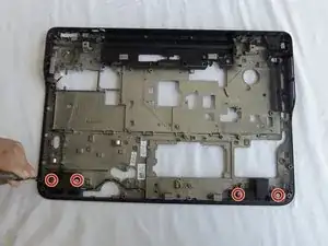
    • Unscrew four 4mm flathead screws with a Phillips screwdriver

  53. 61EdNlSXZYgPs2V6
    61EdNlSXZYgPs2V6
    nhJ4l5ivRZpOQVSL
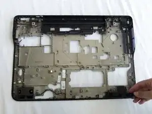
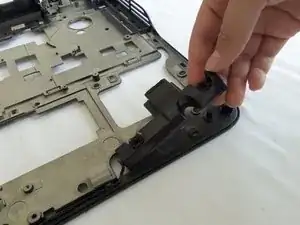
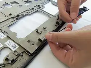
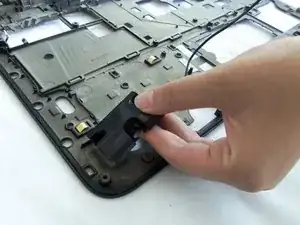
    • Gently lift and remove the right side speaker piece out of its casing.

  54. iMXSYaPTeEDbEaMK
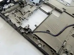
    • Carefully remove the wires from the holdings.

  55. NE6TuhVEBdaBlGdX
    • Gently lift and remove the left side speaker from its housing.

  56. EMisOVZ2VeTXeCbm
    EMisOVZ2VeTXeCbm
    syyvMYVJZDZYRavt
    3jyIQtFZJgZCtgHY
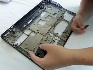
    • Carefully remove the wires from the holdings.

    • Remove the speakers with the cables still attached.

Conclusion

To reassemble your device, follow these instructions in reverse order.

Eddie

Member since: 17/09/15

455 Reputation

One comment

You do not need to go further than step 47 to get to the speakers. That way you avoid messing with main board, and thermal paste and stuff. You can even do it without removing wifi board with some finesse.
Oleg Lego -