Introduction
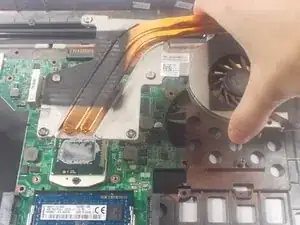
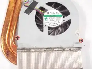
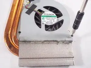
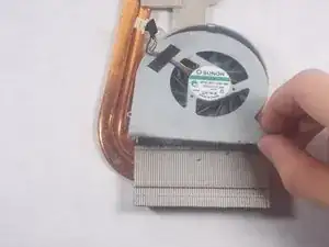
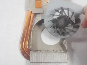
If your laptop critically overheats despite cleaning out the heat sink fins, the cooling fan on the motherboard heat sink assembly may have died, and needs to be replaced in order for the device to function again.
Tools
-
-
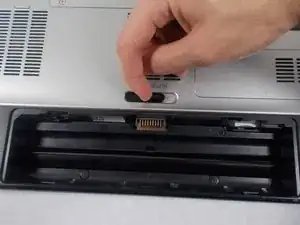
Locate the spring latch on the bottom of the device that will unlatch the battery.
-
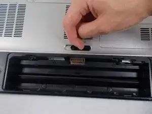
Hold the spring latch in the open position and pull the battery out of its recess.
-
-
-
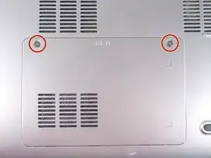
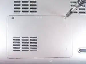
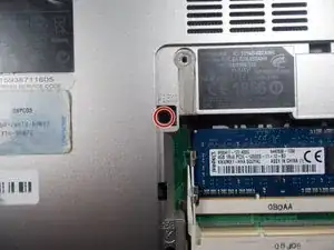
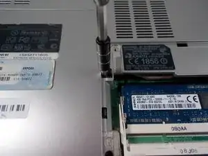
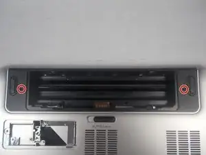
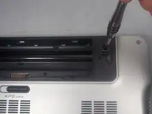
Use a JIS 1 screwdriver to loosen the (2) captive screws from the panel.
-
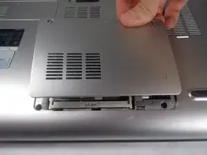
Pull the panel upwards and towards the battery to remove.
-
Put the panel to the side, exposing the RAM.
-
-
-
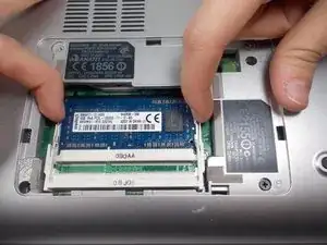
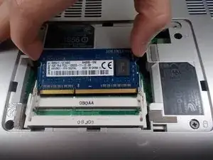
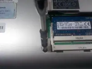
The RAM is held by two spring clips. Pull at the two spring clips and the RAM will move upwards.
-
-
-
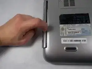
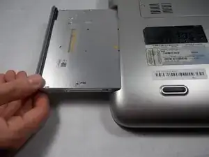
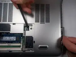
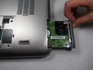
Push the hard drive to the right with a spudger to unseat it from its socket while pulling out the hard drive with your other hand.
-
-
-
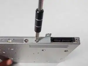
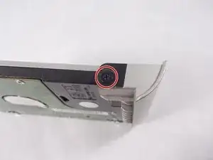
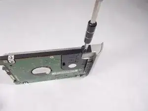
Use a JIS 1 screwdriver to remove (1) 2.5mm screw attaching the plastic cosmetic cover to the hard drive.
-
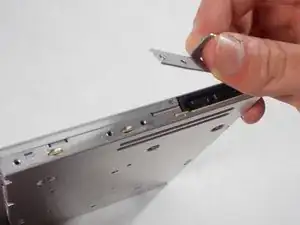
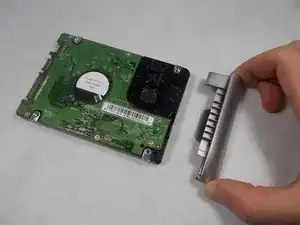
Detach the plastic cosmetic cover from the hard drive.
-
-
-
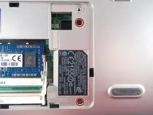
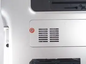
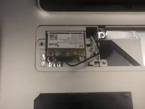
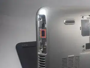
Locate the mini card access panel marked with a radio tower emblem on the bottom of the laptop near the battery bay.
-
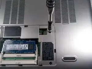
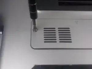
Use a JIS 1 screwdriver to loosen the captive screw securing the panel to the device.
-
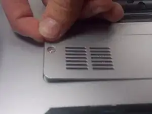
Carefully remove the panel by prying it upwards, unlocking it from the tabs that are securing it in place.
-
-
-
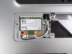
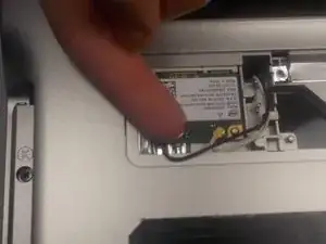
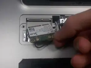
Disconnect the two wires on the mini card by carefully plucking them upwards by the metal contact points at the terminals.
-
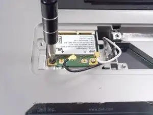
Remove (1) 2mm screw from the bottom left corner of the mini card with a JIS 1 screwdriver.
-
-
-
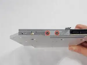
Remove two 4.5mm screws with JIS 1 screwdriver marked by the letter "K" in the optical drive bay.
-
-
-
Remove (2) 4.5mm screws with JIS 1 screwdriver marked by the letter "K"in the hard drive bay.
-
-
-
Open the display to provide room for the palm rest to come out.
-
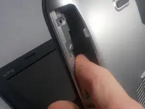
In the hard drive bay, push the "push" pad to lift up the palm rest.
-
-
-
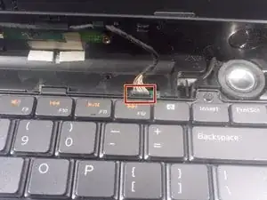
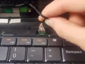
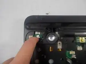
Disconnect the status bar cable by pulling the pin connector upward.
-
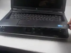
Finish lifting up the palm rest.
-
-
-
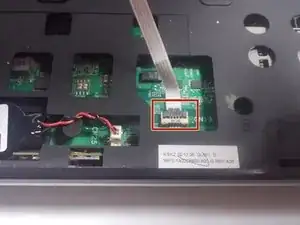
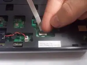
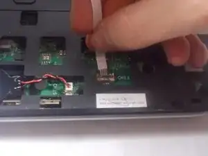
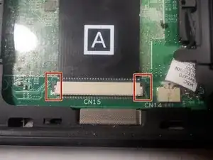
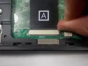
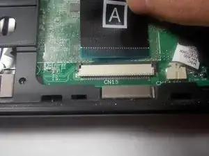
Disconnect the keyboard's ribbon cable marked "A" by pushing out the two black tabs towards the ribbon cable.
-
Remove the cable from its connection terminal by sliding it out. Finish lifting up the keyboard and set it to the side.
-
-
-
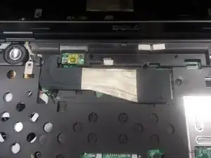
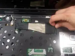
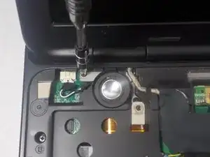
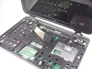
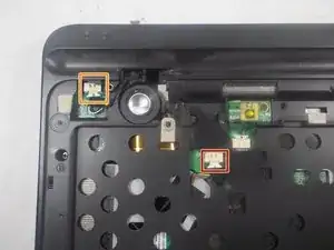
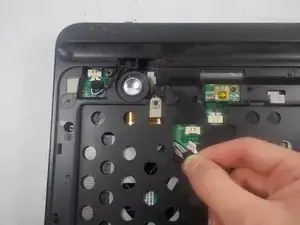
Disconnect the display ribbon cable by pulling the cable to the right by its sheathed plastic connector.
-
-
-
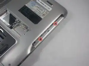
Use a JIS 1 screwdriver to remove (2) 7mm screws on the underside of the laptop near the battery bay.
-
-
-
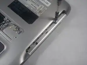
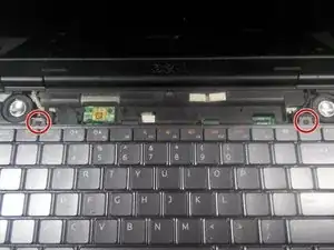
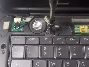
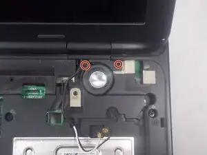
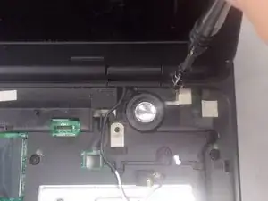
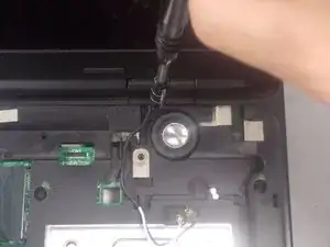
Remove (2) 4mm screws with a JIS 1 screwdriver that are holding down the right side display anchor.
-
-
-
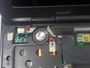
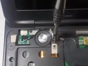
Remove (2) 4mm screws with a JIS 1 screwdriver that are holding down the left side display anchor.
-
-
-
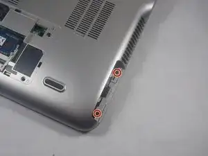
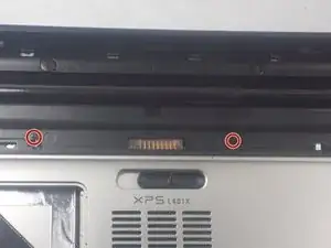
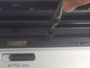
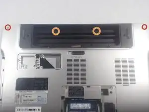
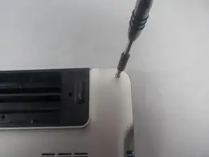
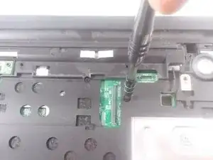
Remove (2) 15 mm screws located on top left and right corners on either side of the battery bay using a JIS 1 screwdriver.
-
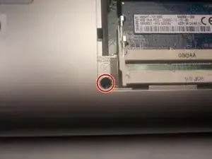
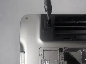
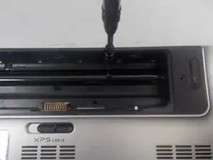
Remove (2) 2mm screws located in the battery bay using a JIS 1 screwdriver.
-
-
-
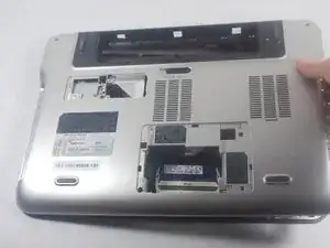
Flip the laptop over.
-
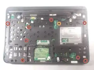
Remove (8) 4mm screws marked with the letter "B" with a JIS 1 screwdriver.
-
Remove (1) 7mm screw marked with the letter "B" with a JIS 1 screwdriver.
-
-
-
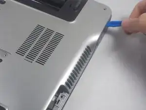
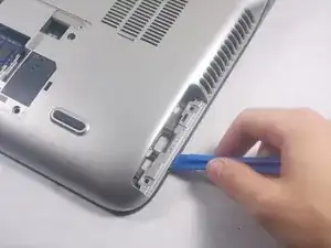
Separate the bottom cover from the top cover with plastic prying tool and finish lifting the bottom cover off.
-
-
-
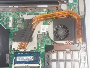
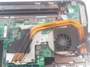
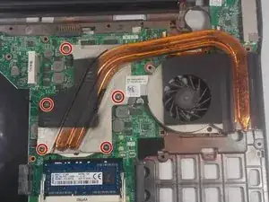
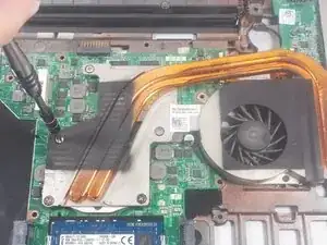
Locate the (5) captive screws that hold down the heat sink assembly to the central processing unit and the graphics processing unit.
-
Unscrew captive screw #1 with a JIS 1 screwdriver for one or two turns and move onto the next screw (#2) and so on, in consecutive order.
-
Continue to slowly loop around the 5 captive screws in order, only loosening the screws one or two turns each time until all screws are completely retracted.
-
-
-
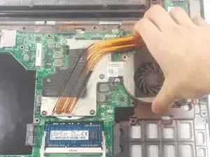
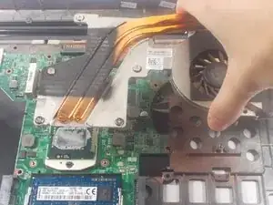
Carefully pull the heat sink assembly upwards off of the motherboard after all the captive screws have been loosened fully.
-
To reassemble your device, follow these instructions in reverse order.
