Introduction
To access the inner workings of the Dell XPS 14 L401X laptop, the bottom cover will need to be removed. The bottom cover protects the inside of the laptop; if it gets damaged, it will need to be replaced.
Tools
-
-
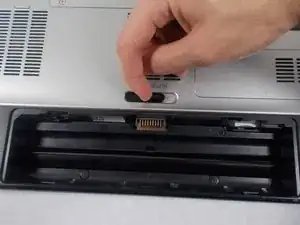
Locate the spring latch on the bottom of the device that will unlatch the battery.
-
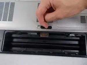
Hold the spring latch in the open position and pull the battery out of its recess.
-
-
-
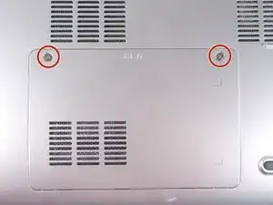
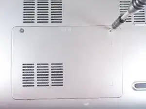
Use a JIS 1 screwdriver to loosen the (2) captive screws from the panel.
-
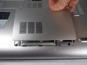
Pull the panel upwards and towards the battery to remove.
-
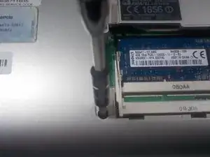
Put the panel to the side, exposing the RAM.
-
-
-
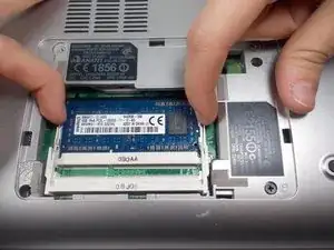
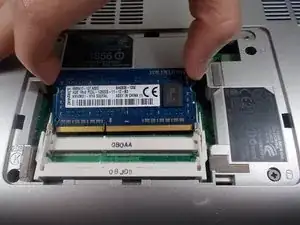
The RAM is held by two spring clips. Pull at the two spring clips and the RAM will move upwards.
-
-
-
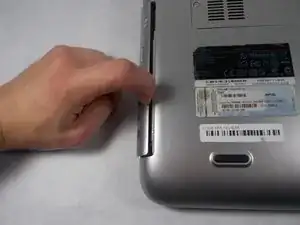
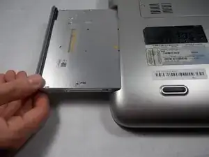
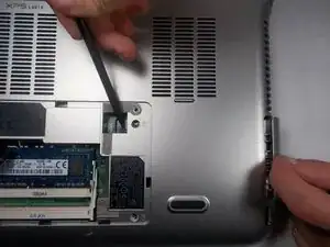
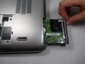
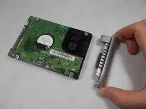
Push the hard drive to the right with a spudger to unseat it from its socket while pulling out the hard drive with your other hand.
-
-
-
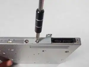
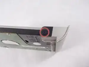
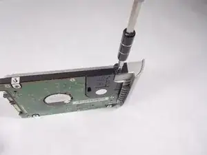
Use a JIS 1 screwdriver to remove (1) 2.5mm screw attaching the plastic cosmetic cover to the hard drive.
-
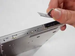
Detach the plastic cosmetic cover from the hard drive.
-
-
-
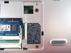
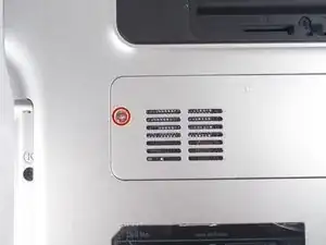
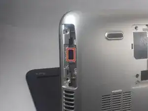
Locate the mini card access panel marked with a radio tower emblem on the bottom of the laptop near the battery bay.
-
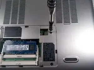
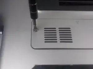
Use a JIS 1 screwdriver to loosen the captive screw securing the panel to the device.
-
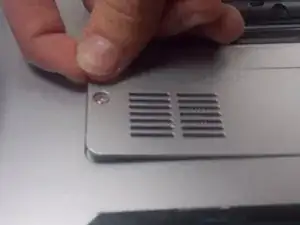
Carefully remove the panel by prying it upwards, unlocking it from the tabs that are securing it in place.
-
-
-
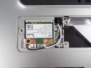
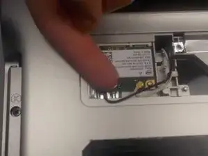
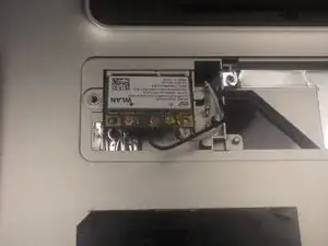
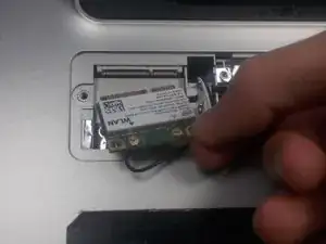
Disconnect the two wires on the mini card by carefully plucking them upwards by the metal contact points at the terminals.
-
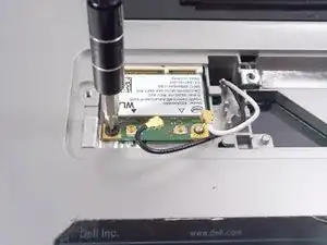
Remove (1) 2mm screw from the bottom left corner of the mini card with a JIS 1 screwdriver.
-
-
-
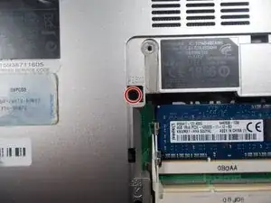
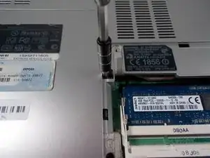
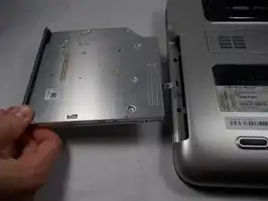
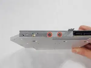
Remove two 4.5mm screws with JIS 1 screwdriver marked by the letter "K" in the optical drive bay.
-
-
-
Remove (2) 4.5mm screws with JIS 1 screwdriver marked by the letter "K"in the hard drive bay.
-
-
-
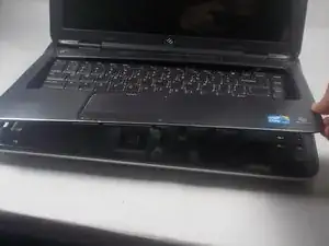
Open the display to provide room for the palm rest to come out.
-
In the hard drive bay, push the "push" pad to lift up the palm rest.
-
-
-
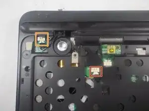
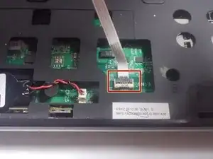
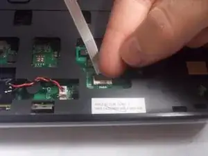
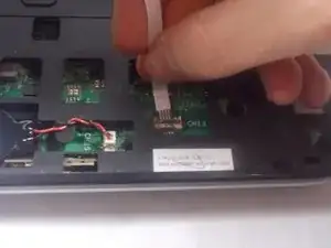
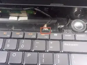
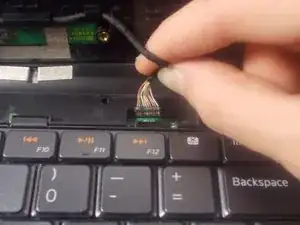
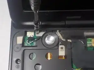
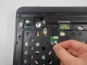
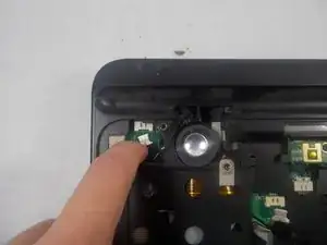
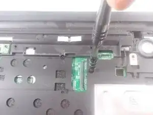
Disconnect the status bar cable by pulling the pin connector upward.
-
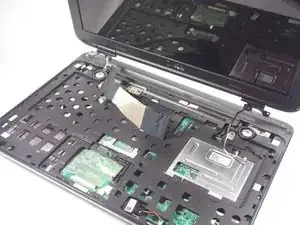
Finish lifting up the palm rest.
-
-
-
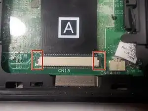
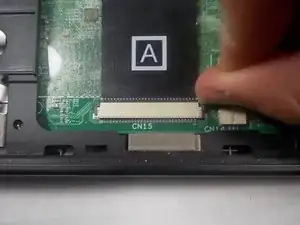
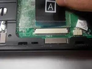
Disconnect the keyboard's ribbon cable marked "A" by pushing out the two black tabs towards the ribbon cable.
-
Remove the cable from its connection terminal by sliding it out. Finish lifting up the keyboard and set it to the side.
-
-
-
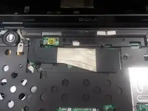
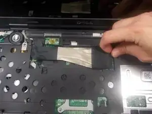
Disconnect the display ribbon cable by pulling the cable to the right by its sheathed plastic connector.
-
-
-
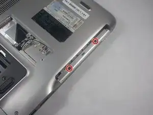
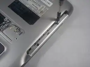
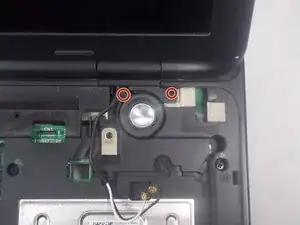
Use a JIS 1 screwdriver to remove (2) 7mm screws on the underside of the laptop near the battery bay.
-
-
-
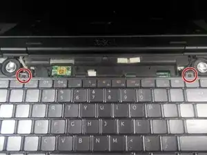
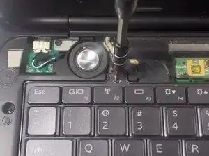
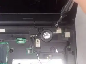
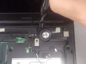
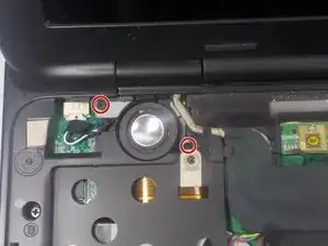
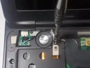
Remove (2) 4mm screws with a JIS 1 screwdriver that are holding down the right side display anchor.
-
-
-
Remove (2) 4mm screws with a JIS 1 screwdriver that are holding down the left side display anchor.
-
-
-
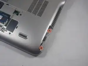
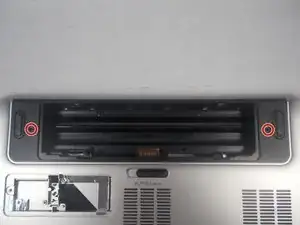
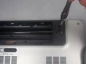
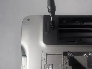
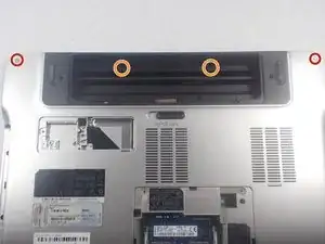
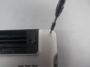
Remove (2) 15 mm screws located on top left and right corners on either side of the battery bay using a JIS 1 screwdriver.
-
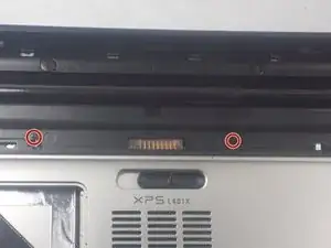
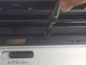
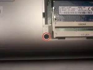
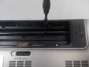
Remove (2) 2mm screws located in the battery bay using a JIS 1 screwdriver.
-
-
-
Flip the laptop over.
-
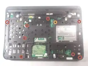
Remove (8) 4mm screws marked with the letter "B" with a JIS 1 screwdriver.
-
Remove (1) 7mm screw marked with the letter "B" with a JIS 1 screwdriver.
-
-
-
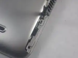
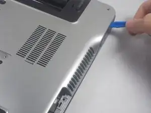
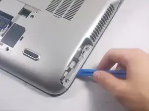
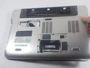
Separate the bottom cover from the top cover with plastic prying tool and finish lifting the bottom cover off.
-
To reassemble your device, follow these instructions in reverse order.
