Introduction
The motherboard replacement for the OptiPlex FX170, compared to other computers, is actually rather painless. One should, however, be familiar with preventing electro-static dischage (ESD) damage to electronics.
Tools
-
-
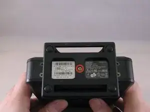
With the base stand facing upwards, unscrew the 6mm Phillips #2 screw.
-
Pull the base stand straight up from the device.
-
-
-
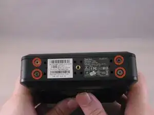
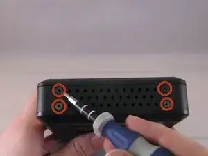
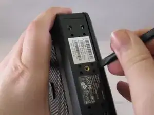
Unscrew and remove the eight 4mm Phillips #0 screws (four on top, four on bottom) from the top and bottom of the device.
-
-
-
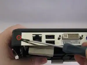
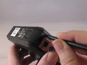
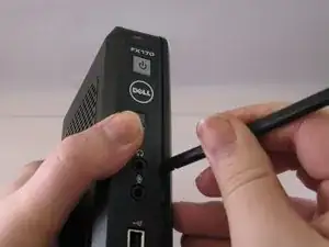
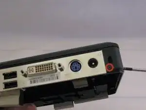
Run the flat side of the spudger along the entire line of the case starting from the back where the power plug and a small screw are located.
-
-
-
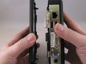
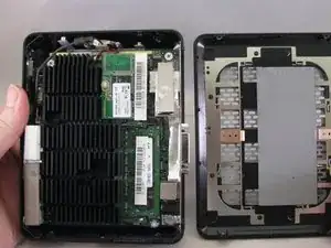
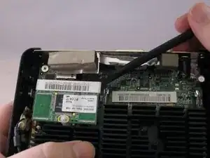
Once the clips have been released, gently disengage the cover from the rest of case by pulling in opposite directions.
-
-
-
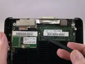
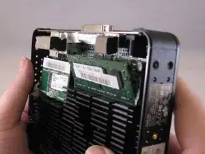
Using fingers, push the clips on either side of the RAM. The RAM will pop up at a 45 degree angle when both clips are disengaged.
-
-
-
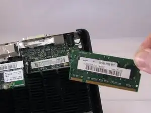
Using the spudger, gently push on the underside of the memory board to loosen it. Gently grasp each side and pull up to release the memory board.
-
-
-
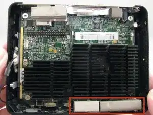
Remove the two foam bumpers that lie on top of the two front USB ports with fingers. Do not throw them away.
-
-
-
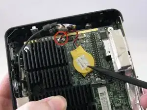
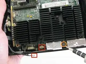
Disconnect the speaker cable from the motherboard by gently pulling it straight up to disengage it from the port.
-
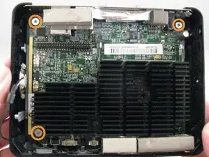
Remove the four 4mm Philips #0 screws that secure the motherboard to the case.
-
-
-
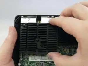
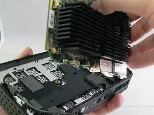
Gently grasp the motherboard by the heat sink (the black finned piece). Lift the motherboard at an angle such that the ports along the back side come up first.
-
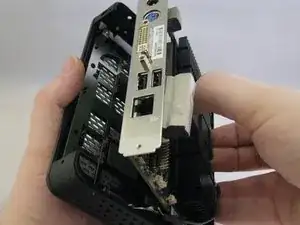
Continue lifting the motherboard, then slowly tilt the piece off to the right to break the Mylar tape over the front USB ports.
-
To reassemble your device, follow these instructions in reverse order.
